Drawbacks of Heterodyne Transmitter – Mixing Spurs
In the previous blog, we discussed about the first drawback of the Heterodyne transmitter which is DC offset. The second drawback is Mixing Spurs, which will be discussed in this blog.
What is Mixing Spurs?
In simple language, if there are two mixer stages then there will be mixing spurs. One of the most important issues in dual conversion is mixing spurs. It is always assumed that our local oscillator produces a fundamental frequency of ‘A cos wLOt’ however, this is not true in the real world as we face a problem which is the mixers produce harmonics. So we will have additional components called harmonics (2wLOt, 3wLOt…). For example, if we have three mixing spurs in a system and if these signals are not removed completely, they will be translated inside our channel. If translated, we will have these interferers included within our channel corrupting it. Though these interferers will not have high amplitude due to the filters within the system.
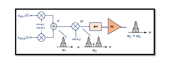
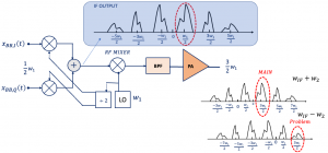
One of the drawbacks of heterodyne transmitters is mixing spurs. Imagine that in the below structure the local oscillator at the first step is experiencing the non-linearity and harmonics, so what kind of outputs we will have here? As shown below, the fundamental frequency is w1/2 but the third harmonic is 3 x w1/2 and the fifth harmonic is 5 x w1/2 their amplitude is decreasing as we are going to higher harmonics hence, we can ignore the seventh, and ninth, and the rest.

Imagine that these channels are mixed with the fundamental frequency of the second mixer assuming that here the second mixer has no harmonics in theory and is perfect. So we are mixing all these channels with the second mixer where w2 is the frequency of the second mixer. The outputs we will have is the combination (wIF+w2) and difference (wIF-w2). For the combination part, we can get rid of other channels using the bandpass filter (BPF) in the structure. However, for the difference part (wIF-w2), 3w1/2 is a problem, as it gets translated directly into our channel and corrupts it, this is the mixing spur which is emerged from the third harmonic of the first mixer. We have to get rid of this component, the third harmonic of the first mixer, as you see if you have a third harmonic problem at the output it will be translated in the same frequency as the main channel.
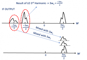
There are other problems associated with mixing spurs, let’s say that our second mixer is also experiencing a harmonic problem similar to the first one. So what kind of spurs do we have now? Imagine that we have –3w1/2, which is the result of the first LO 3rd harmonic and it’s a negative part, we have positive and negative. This will be mixed with the third harmonic of the second mixer. Now we’re assuming that our mixer is actually experiencing non-linearity and the second mixer also has non-linear harmonics so here as you see we have the third harmonic and fifth harmonic, mixing with the 5th harmonic of the second mixer and now we have two channels.
These two channels are translated to the main channel, the same band frequency and they will corrupt our data. Now instead of having this main channel here which is our main data, we have two channels with the same frequency. They are combining with our channel and corrupting our data. The mixing forms the critical part of this kind of transmitter, so we have to be careful. It generally occurs when you have two stages of mixers as also seen in receivers. If you have two stages, there will be harmonic problems and it’s almost impossible to avoid. So while designing we have to be careful about the 3rd and 5th harmonic of the first and second mixer, design them symmetrically and try to linearize the mixers.


