Transmission Line Time Domain Equations
In previous blogs, we discussed about wave propagation where we said that the voltage on the transmission line will propagate and have wave like behaviour. In this section, we will prove this theory. We can understand the behaviour of voltage and current on the transmission line from time domain equations. Hence, we will derive the time domain equations.
How to convert Phasor Equation to Time Domain Equation?
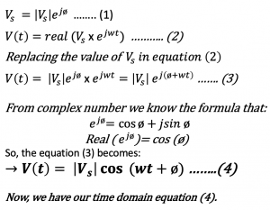
In order to get the time domain equation we need to convert the phasor equation to the time domain. From the basics we know that if you have a source voltage, it can be any voltage on our circuit, then we can write it in the form of |Vs|cos (wt +ø) where Vs is the amplitude and ø is the phase. So, the phasor of this equation would be Vs=|Vs|ejø. We would just need two things to write the phasor; amplitude and phase. Now, we will convert the phasor to the time domain. First, we will multiply the phasor with ejwt and then we are going to say the real part of this expression: So, what we did to convert the phasor to a time domain signal is first to multiply it by ejwt and then take a real.
We have obtained the phasor equation for our transmission line in the previous blog ‘’Transmission line phasor equations’’. We obtained the phasor form equations for V(z) and I(z). So similar to the above method we can derive the time domain equation from the phasor equation as shown below:
So as you see here we are getting to that point. The voltage is a function of location and time. From the above equation (5) we can see that we have both these variables within our cosine so it means that this cosine changes with time and with the location. How it changes we will see now.
Example to prove Wave Propagation
Let’s say we have a lossless transmission line where ? = 0. From the previous blog, we know that the transmission coefficient gamma (γ) is equal to α+ßj, α becomes 0 in lossless. So if ? = 0 then |V0+| e–αz in equation (5) equals 1. And also ø+ and ø– equals 0. We are finally left with two equations (1) and (2) shown below:
Now we focus on the first equations. From ‘’Transmission line phasor equations’’ we said that the e-yz term represents wave propagation in the +z direction, so let’s prove it.
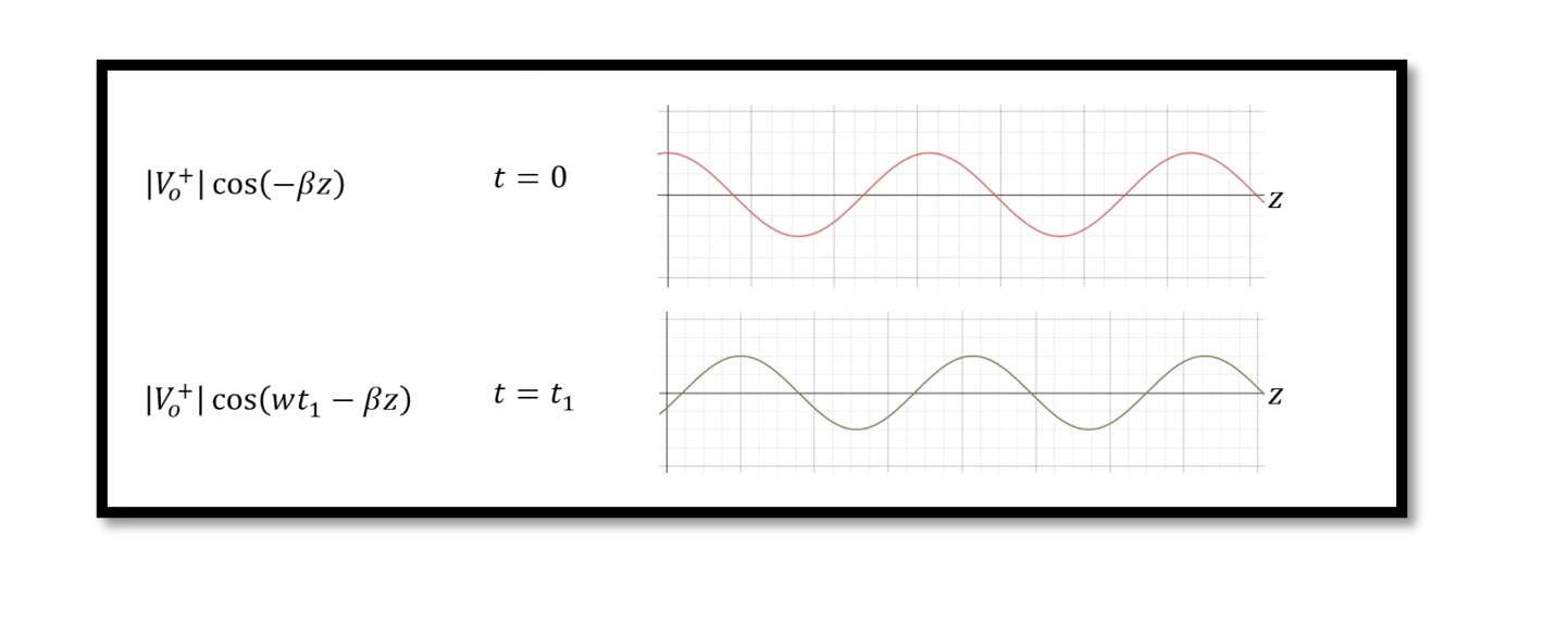
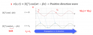
 We will show it in two values of time and in a positive direction. So at t=0 we will have |V0+| cos (-ßz), voltage changes for different positions. So, the voltage at any location will not be equal, that’s distributed analysis as we have already discussed in the previous blog. But in lumped analysis the voltage is constant. This time domain equation shows that voltage is different at different locations and is a function of time and location.
 Now we will see the propagation at t=t1. We will have |V0+| cos (wt1-ßz), so it shifts the wave to the right side, the shift is equal to wt1. Now we can see propagation in the +z direction. So each time the value of t changes the wave shifts to the right side. This is called the wave propagation that we just proved. We observed the first part of the wave assuming there is only the first part but what happens if we have the second part of the wave? In the next blog we will talk about the second part of the equation. Which is called Reflection Equation for reflection voltage.


