Transmission line terminated by a load
Transmission line terminated by a load
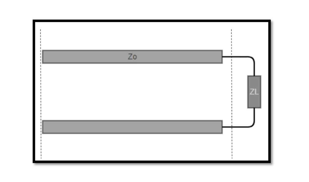
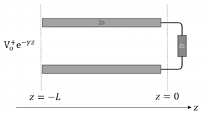
Let’s consider a simple example of a transmission line terminated by a load. The transmission line consists of a pair of conductors (wires) separated by a dielectric material. At one end, the transmission line is connected to a signal source, and at the other end, it is connected to a load. In the image below, we can see a transmission line connected to a signal source (represented by the voltage source) at one end and to a load (represented by the resistor) at the other end.

 The signal source generates an electrical signal that travels along the transmission line towards the load. The electrical signal is a high-frequency alternating current (AC) signal that is carried by the conductors of the transmission line. At the load end of the transmission line, the signal encounters the load impedance (in this case, a resistor). If the impedance of the load matches the characteristic impedance of the transmission line, then the electrical signal will be efficiently transferred from the transmission line to the load. This is known as impedance matching.
In the case of impedance matching, the signal passes through the load without any significant reflection or distortion. The amount of power delivered to the load is determined by the voltage and current levels of the signal and the impedance of the load. However, if the impedance of the load does not match the characteristic impedance of the transmission line, then some of the signal will be reflected back to the source. This can cause signal distortion and a loss of signal strength. In extreme cases, it can cause damage to the electronic components.
To avoid this problem, it is important to ensure that the load impedance is matched to the characteristic impedance of the transmission line. This can be achieved by using matching networks or impedance transformers, which can modify the impedance of the load or the transmission line to achieve impedance matching.
Example of a transmission line terminated by a load
Let’s consider a specific example to illustrate a transmission line terminated by a load. Suppose we have a coaxial cable with a characteristic impedance of 50 ohms. At one end of the coaxial cable, we have a signal generator that generates a 1 GHz sine wave with an amplitude of 1 volt. At the other end of the coaxial cable, we have a resistor of 75 ohms.
In this case, we have a mismatch between the impedance of the load (75 ohms) and the characteristic impedance of the transmission line (50 ohms). As a result, some of the signal energy will be reflected back to the signal source, while some will be absorbed by the load.
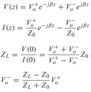
Using the reflection coefficient formula, we can calculate the amount of reflected energy at the load end of the coaxial cable:
Γ = (ZL – Z0) / (ZL + Z0)
where Γ is the reflection coefficient, ZL is the load impedance (75 ohms), and Z0 is the characteristic impedance of the coaxial cable (50 ohms).
Substituting the values, we get:
Γ = (75 – 50) / (75 + 50) = 0.2
This means that 20% of the signal energy will be reflected back to the signal source, while the remaining 80% will be absorbed by the load. The reflected energy will cause interference and reduce the overall signal strength.
To improve the situation, we can use a matching network or an impedance transformer to match the load impedance to the characteristic impedance of the coaxial cable. This will reduce the amount of reflected energy and improve the efficiency of the transmission line.
What is Reflection Coefficient?
The voltage reflection coefficient, also known as the voltage standing wave ratio (VSWR), is a measure of the amount of reflection that occurs when an electromagnetic wave propagates along a transmission line and encounters an impedance mismatch at the load end. It is a dimensionless quantity that describes the ratio of the amplitude of the reflected wave to the amplitude of the incident wave.
The voltage reflection coefficient is calculated using the following formula:
Γv = (Vr / Vi)
where Γv is the voltage reflection coefficient, Vr is the amplitude of the reflected voltage wave, and Vi is the amplitude of the incident voltage wave.
The voltage reflection coefficient can be expressed in terms of the impedance mismatch between the load and the characteristic impedance of the transmission line. It is given by:
Γv = (ZL – Z0) / (ZL + Z0)
where ZL is the load impedance and Z0 is the characteristic impedance of the transmission line.
A value of zero for the voltage reflection coefficient indicates perfect impedance matching, meaning that all of the incident wave energy is absorbed by the load without any reflection. A value of 1 indicates complete reflection of the incident wave, meaning that none of the wave energy is absorbed by the load and all of it is reflected back towards the source. In general, the lower the voltage reflection coefficient, the better the efficiency of the transmission line.


