Reflection and Standing Waves in Transmission Line
When does Reflection occur in Transmission Line?
Impedance mismatch in transmission line can cause impedance mismatch which is the cause of reflection. A wave travelling through transmission will obviously face characteristic impedance. Read more about characteristic impedance. When there is mismatch of impedance of source or load with characteristic impedance of transmission line then we get some energy reflected to source. The standing wave is formed when incident wave and reflected wave combines. We can say that impedance mismatch is the primary reason for reflection in transmission line.
What are Standing Waves in Transmission Lines?
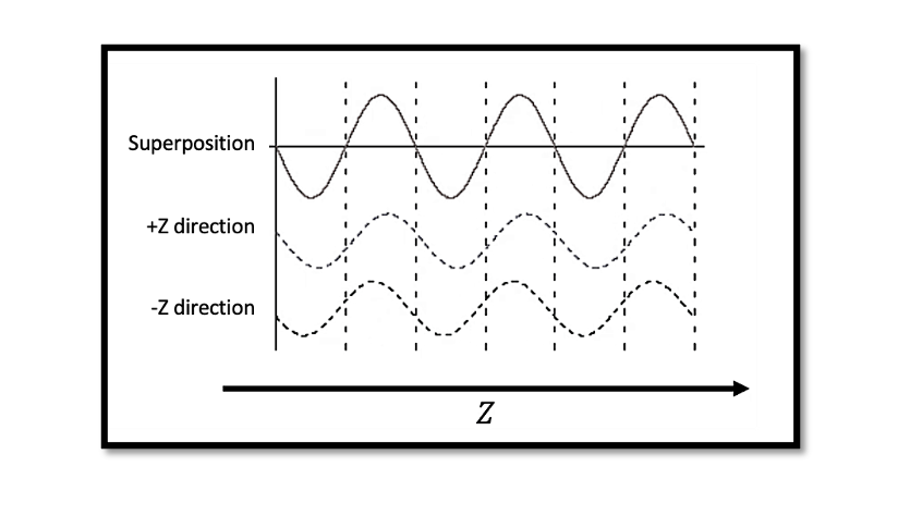
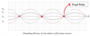
The superposition of the incident and reflected waves results in superposition, as you will see in below example and figure. At fixed points these combines which then results in waves that looks like standing, it is formed at the nodes (fixed point) at which the voltage is constant (zero).
Relation between Reflection and Standing Waves
The formation of standing waves are as result of reflection and incident waves hence we can say that the reflection and standing waves are closely related. Some of the energy is reflected to source along a transmission line because of impedance mismatch. The combination of this reflected wave with standing wave forms the standing wave.
Some of the effects of having reflection and standing waves along the transmission line can be signal distortion, power loss and interference. Due to energy dissipation in transmission lines there can be power loss for standing waves. On the other hand the reflected wave phase and amplitude depends on impedance and length which can lead to signal distortion errors and interference.
In summary the reflection and standing waves are common phenomena that occur in transmission lines due to impedance mismatch. They can cause signal distortion, power loss, and interference, leading to errors in the transmitted signal. Understanding these phenomena is important in designing and optimizing transmission lines for efficient signal transfer.
Example to show Standing Waves in Transmission Line
What happens when we have reflections, meaning now we are considering the second part of the equation, let’s write the equations as equation (3) and (4).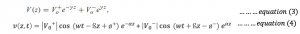
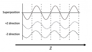
In a previous blog Transmission Line Reflection Equation we showed the equation and observed it assuming that the positive and negative absolute values are 1 and the initial phase is 0. We are going to have superposition and from there we can find the standing wave formula. From the below figure, you can see the second wave is in the positive direction (+z) and then there is another wave reflecting which is in the negative direction (-z). This is called a reflected wave.
In the upcoming section, we’re going to show how this happens and when we will have a reflected wave. For this blog, we are assuming that we have the condition of reflected waves.
When we add the second and third waves together what we get is standing waves. The voltage at the fixed points is always constant, it’s 0 but it changes at other points. The fixed-point voltage is not changing there so you can see from here that you have a different kind of voltage at other points and this is how you can explain the standing wave formation The amplitude is not constant in standing waves, it keeps changing.
Till now we were discussing about lossless transmission lines, but what happens when there is a loss? So ? ≠ 0.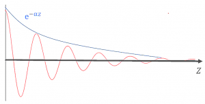
You get this curve for the function of z, e–?z so if you keep going to the plus z direction eventually the amplitude is going to shrink because of the loss in the transmission line and at the end, there won’t be any wave because it is absorbed by resistor or conductor. That’s what happens if you have. But when there is no loss you see pure sine wave assuming that amplitude is not attenuated but because of losing power the amplitude gets shorter and shorter.

Learn more about this topic by taking the complete course ‘RF Microwave and Radio Frequency Transmission Theory Online Course – RAHRF200’. Watch the course videos for more detailed understanding. Also checkout other courses on RF system and IC design on https://rahsoft.com/courses/. Rahsoft also provides a certificate on Radio Frequency. All the courses offer step by step approach.
You may also like
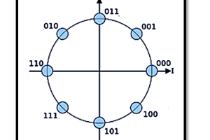
Understanding Quadrature Amplitude Modulation (QAM) and Its Applications