Understanding Power versus Time in Wireless Communication Systems
Introduction:
Power versus time analysis in wireless communication systems is a critical aspect that delves into the dynamic interplay between power levels and temporal variations. In this exploration, we navigate the intricacies of measuring power over time, a vital consideration for optimizing the performance and reliability of communication systems. Utilizing tools such as spectrum analyzers and power sensors, and employing internal and external triggers, engineers gain insights into how RF power evolves across different time spans. This analysis becomes particularly relevant in scenarios where seamless transitions between transmission and reception are imperative, such as in Time Division Duplexing (TDD) systems. In this journey, we unravel the methodologies and considerations that shape our understanding of power versus time dynamics.
Although a specific frequency is set in wireless communication systems, the dynamics of power and time play crucial roles, each representing an axis in the analysis. Power versus time (PVT) is commonly expressed in decibels relative to milliwatts (dBm), providing a metric for measuring power levels within specific time slots or intervals. The utilization of a trigger signal is integral to precisely measure power where needed at a specific moment. This concept becomes particularly relevant in Time Division Duplexing (TDD) systems, where the transmission and reception occur within the same frequency band, necessitating seamless switches between the two functions. Managing this transition involves selecting the appropriate components such as power amplifiers, Low Noise Amplifiers (LNAs), and handling the up and down conversion processes. The timing precision is crucial, requiring meticulous attention to factors like on and off times, settling times, and adherence to a predefined power mask that dictates permissible power levels based on the allocated time slot. This intricate interplay ensures the efficiency and reliability of wireless communication systems.
Precision Measurement with Trigger Signals in Power versus Time Analysis

In the context of power versus time analysis, let’s delve into a practical example involving a trigger signal, represented by the green signal in our illustration. When the trigger signal rises, it serves as a signal to initiate the measurement of power levels. For instance, at a specified moment, denoted as t1 in this illustration, the power level is precisely measured. It’s crucial to note that this analysis operates in the time domain rather than the frequency domain, focusing on the power level variation over time. While the chart doesn’t explicitly depict the frequency and bandwidth details, the measurement is conducted on the specified frequency and bandwidth parameters. During the trigger signal phase, if the equipment allows, one can opt for sweep measurements across the entire time span or choose specific points for measurement. In the presented scenario, t1 and t2 are arbitrarily chosen instances, but the flexibility exists to place them strategically based on specific requirements and system specifications. This adaptability ensures that measurements align with desired criteria, showcasing the versatility and precision achievable in power versus time analysis.
Exploring Power Detectors and Spectrum Analyzers in Power versus Time Analysis

When delving into the measurement of power versus time, the choice of instrumentation plays a crucial role. Two primary tools for this analysis are spectrum analyzers and power sensors. Ideally, incorporating an external trigger signal provides precise control over when the measurement equipment captures power levels. However, modern power sensors and spectrum analyzers often feature internal triggers, specifically based on envelope power. This internal trigger activates the measurement process once the envelope power reaches a predetermined level.
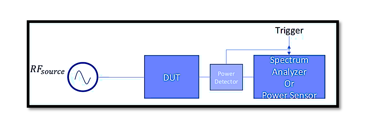
The decision to utilize internal or external triggers depends on the application’s requirements. Having the capability for an external trigger offers versatility and control. To set up the measurement, place your Device Under Test (DUT) – the RF source – at the input. Optionally, you can include a power detector, which serves as a through line with a small coupling path. This coupling path transforms the RF signal into a DC signal, which then enters the spectrum analyzer or power sensor. The power detector, acting based on power or envelope power level, serves as a time reference for the analysis.
In some scenarios, omitting the power detector and using a through line is preferred. In such cases, the external trigger becomes crucial. The external trigger could be a baseband signal that you want to compare with the power level. For instance, it could be the controlled signal of a switch. By observing the time it takes for the RF power to reach its peak after toggling the control signal of the DUT, you gain valuable insights into the dynamic behavior of the system. This dual approach with internal and external triggers enhances the flexibility and applicability of power versus time analysis across diverse scenarios.
Conclusion:
The investigation into power versus time not only unravels the complexities inherent in wireless communication systems but also highlights the diverse tools and techniques available for precise measurements. Spectrum analyzers, power sensors, and the strategic use of triggers contribute to a nuanced understanding of how power levels evolve over time. Whether opting for internal triggers based on envelope power or leveraging external triggers for more controlled measurements, engineers have the flexibility to adapt their approach based on specific applications. By comprehensively examining the role of power detectors, coupling paths, and external triggers, we uncover the intricate dance between power and time, shedding light on the temporal dynamics that underpin the reliability and efficiency of wireless communication systems. This exploration serves as a guide for engineers seeking to master the art of power versus time analysis in their quest for optimal system performance.

Learn more about this topic by taking the complete course ‘Introduction to RF Testing Fundamentals and RF Test Architecture – RAHRF412’. Watch the course videos for more detailed understanding. Also checkout other courses on RF system and IC design on https://rahsoft.com/courses/. Rahsoft also provides a certificate on Radio Frequency. All the courses offer step by step approach.
Tag:Power, PowerVsTime, Time


