PLL: XOR Gate Phase Detector
Let’s start discussing one of the fundamental blocks in a Phase-Locked Loop (PLL): the phase detector. Specifically, we’ll look at a simple phase detector that uses an XOR gate.
XOR Gate Basics
An XOR (exclusive OR) gate outputs a high signal (1) only when the inputs are different. For inputs A and B, the XOR gate follows these rules:
- If A = 0 and B = 0, the output is 0.
- If A = 1 and B = 0, the output is 1.
- If A = 0 and B = 1, the output is 1.
- If A = 1 and B = 1, the output is 0.

Inputs and Outputs
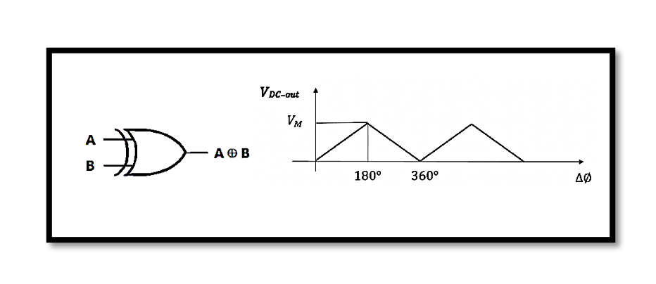
In the diagram, we have two digital signals, A and B, which represent the inputs to the XOR gate. These signals are typically periodic waveforms with a certain frequency.
- The first waveform is A, which alternates between high (1) and low (0) at regular intervals.
- The second waveform is B, which also alternates similarly but may have a phase difference compared to A.
The XOR gate compares these inputs and produces an output that reflects their phase difference.
Output Signal
The output signal from the XOR gate is high (1) when A and B are different and low (0) when they are the same. This output is shown as a series of pulses, where the duration of the pulses depends on the phase difference between A and B.

DC Output (VDC-out)
The output of the XOR gate is fed into a low-pass filter, which smooths the pulses into a DC level. The DC level, 𝑉𝐷𝐶−𝑜𝑢𝑡, is proportional to the duty cycle of the XOR output. The duty cycle is the fraction of time the output is high in one period.
- When A and B are perfectly in phase (0° phase difference), the XOR output is always 0, resulting in 𝑉𝐷𝐶−𝑜𝑢𝑡 =0.
- When A and B are 180° out of phase, the XOR output is high for half the period, resulting in 𝑉𝐷𝐶−𝑜𝑢𝑡 = 𝑉𝑀/2 (where 𝑉𝑀 is the peak voltage).
The relationship between 𝑉𝐷𝐶−𝑜𝑢𝑡 and the phase difference (∆φ) is linear, as depicted in the bottom graph of the diagram. As the phase difference varies from 0° to 360°, 𝑉𝐷𝐶−𝑜𝑢𝑡 increases to 𝑉𝑀 and then decreases back to 0.
So, in summary the XOR gate phase detector is a simple and effective way to measure phase differences between two digital signals. The output DC level gives a direct indication of the phase difference, which can be used in PLL circuits to maintain synchronization between the signals.
Take our entry level course (Below) for free using coupon code RAHRF101BLOG
RF Fundamentals, Basic Concepts and Components – RAHRF101
For limited time take an additional 10% off of all our courses using coupon code RFCERT10
Rahsoft RF Certificate and courses
Alternative Phase Detector using a MOS Switch
Continuing from our discussion on phase detectors in Phase-Locked Loops (PLLs), let’s explore an alternative approach using a single MOS switch. This approach is sometimes referred to as a “poor man’s phase detector.” This method utilizes a MOS switch to mix two input signals. The output of this mixing process, after passing through a low-pass filter (LPF), provides a signal indicative of the phase difference between the inputs. In this setup, the output signal 𝑋𝑜𝑢𝑡(𝑡) of the mixer is the product of two cosine signals, mathematically represented as:

When these two signals are mixed, the output consists of two components:
- A component at the sum of the frequencies (𝜔1+𝜔2)
- A component at the difference of the frequencies (𝜔1−𝜔2).
However, when 𝜔1=𝜔2, the high-frequency components are filtered out by the LPF, leaving us with the low-frequency component:


Graphical Representation
The graph in the slide shows 𝑉𝐷𝐶−𝑜𝑢𝑡 versus the phase difference Δ𝜙:
- When Δ𝜙=0, 𝑉𝐷𝐶−𝑜𝑢𝑡. is at its maximum positive value.
- When Δ𝜙=90∘, 𝑉𝐷𝐶−𝑜𝑢𝑡is zero.
- When Δ𝜙=180∘, 𝑉𝐷𝐶−𝑜𝑢𝑡is at its maximum negative value.
This sinusoidal relationship indicates that the DC output voltage varies as a cosine function of the phase difference.
The schematic diagram illustrates the MOS switch phase detector, showing how it multiplies the input signals 𝑆1 and 𝑆2, producing the mixer output that, after LPF smoothing, gives 𝑉𝐷𝐶−𝑜𝑢𝑡. This approach is a straightforward, cost-effective method for phase detection, providing a useful alternative in PLLs.
The MOS switch phase detector, showing how it multiplies the input signals 𝑆1 and 𝑆2, producing the mixer output that, after LPF smoothing, gives 𝑉𝐷𝐶−𝑜𝑢𝑡. This approach is a straightforward, cost-effective method for phase detection, providing a useful alternative in PLLs.
Summary
This phase detection method utilizes a single MOS switch to mix two input signals, creating an output indicative of their phase difference. The mixer combines the signals, and after passing through a low-pass filter, the resulting DC output voltage varies as a cosine function of the phase difference. This approach is cost-effective and straightforward, making it a practical alternative for phase detection in Phase-Locked Loops (PLLs). The output’s DC level provides a clear representation of the phase difference, essential for maintaining signal synchronization in PLL systems.

Learn more about this topic by taking the complete course ‘Phase Lock Loop System Design Theory and Principles RAHRF469’. Watch the course videos for more detailed understanding. Also checkout other courses on RF system and IC design on https://rahsoft.com/courses/. Rahsoft also provides a certificate on Radio Frequency. All the courses offer step by step approach.
Tag:PD, Phase Detector, PLL, XOR Gate


