Ripple in Phase-Locked Loops (PLLs)
Phase-Locked Loops (PLLs) are critical components in a variety of electronic systems, ensuring accurate and stable frequency and phase synchronization. However, one common issue that can degrade the performance of PLLs is voltage ripple. This blog will delve into the ripple problem in PLLs, its causes, effects, and solutions, particularly focusing on the use of a low-pass filter (loop filter) to mitigate this issue.
What is Voltage Ripple in PLLs?
Voltage ripple in PLLs refers to unwanted fluctuations or noise in the control voltage (Vctrl) that regulates the voltage-controlled oscillator (VCO). These fluctuations, often manifesting as high-frequency pulses or ripples, can significantly affect the stability and accuracy of the PLL’s output. Ripple problems can cause jitter and frequency instability, leading to degraded performance in applications requiring precise timing, such as communication systems.
Causes of Ripple in PLLs
- Power Supply Noise: Variations in the power supply introduce noise into the PLL circuitry, affecting the VCO and other components.
- Thermal Noise: Electronic components generate thermal noise due to the random motion of electrons, contributing to phase jitter in the PLL.
- Loop Filter Design: An improperly designed loop filter can introduce ripples and noise.
- Reference Signal Noise: Noise in the reference signal is transferred to the PLL output, causing ripples.
- Component Imperfections: Imperfections in resistors, capacitors, and inductors contribute to noise and instability.
- Digital Switching Noise: Switching noise from digital circuits can couple into the analog parts of the PLL, causing ripples.
Effects of Ripple in PLLs
- Jitter: Ripples result in phase jitter, causing variations in the timing of the output signal, which is critical in communication systems.
- Frequency Instability: Ripple can cause the PLL to lock onto the wrong frequency or produce an unstable frequency output.
- Data Integrity Issues: Jitter and phase noise can lead to data errors and reduced signal integrity in digital communication systems.
Fixing Voltage Ripple: The Role of the Low-Pass Filter
The primary solution to the ripple problem in PLLs is the insertion of a low-pass filter, commonly referred to as the loop filter, between the phase detector (PD) and the VCO. This filter is designed to suppress the high-frequency pulses in the control voltage (Vctrl), resulting in a smoother and more stable DC voltage.
How the Low-Pass Filter Works
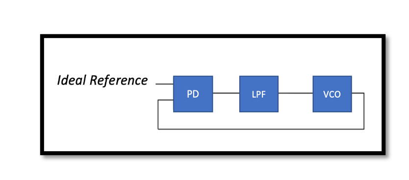
Diagram of a PLL with Loop Filter

- Phase Detector (PD): The PD compares the phase of the input reference signal with the phase of the VCO output. It generates an error signal (Vctrl) proportional to the phase difference. This signal typically contains high-frequency components (ripples).
- Low-Pass Filter (LPF): The LPF filters out high-frequency components from the error signal, smoothing out the ripples and producing a more stable DC voltage.
- Voltage Controlled Oscillator (VCO): The VCO generates an output signal whose frequency is controlled by the smoothed voltage from the LPF. This output is fed back to the PD for comparison with the reference signal.
The PD produces a control voltage (Vctrl) that can contain high-frequency ripples due to rapid changes or noise in the phase difference between the reference signal and the VCO output.
Applying a low-pass filter to the Vctrl signal attenuates high-frequency ripples, leaving a smoother DC component. This reduces noise and fluctuations, providing a cleaner control voltage to the VCO. With a cleaner control voltage, the VCO generates a more stable and accurate output frequency, which is crucial for the proper functioning of the PLL.
Take our entry level course (Below) for free using coupon code RAHRF101BLOG
RF Fundamentals, Basic Concepts and Components – RAHRF101
For limited time take an additional 10% off of all our courses using coupon code RFCERT10
Rahsoft RF Certificate and courses
Mitigation Techniques Beyond the Low-Pass Filter
- Improved Power Supply Filtering: Using low-noise power supplies and effective decoupling can reduce power supply noise.
- Thermal Management: Proper thermal design to minimize temperature variations can help reduce thermal noise.
- High-Quality Reference Oscillators: Using low-noise reference oscillators can reduce the amount of noise transferred to the PLL output.
- Component Quality: Selecting high-quality components with low noise characteristics can improve overall PLL performance.
- Shielding and Layout: Proper PCB layout and shielding techniques can minimize the impact of digital switching noise and other interference.
Conclusion
Voltage ripple is a significant issue in PLLs, potentially causing jitter and frequency instability. The primary solution involves using a low-pass filter to smooth out the control voltage, ensuring a stable and accurate output from the VCO. Understanding the causes and effects of ripple, along with employing effective mitigation techniques, can lead to the design of more robust and reliable PLLs. By addressing these factors, engineers can enhance the performance of systems that rely on precise frequency and phase synchronization. By focusing on the design and implementation of a well-tuned loop filter, engineers can significantly reduce the ripple problem in PLLs, ensuring optimal performance in critical applications.

Learn more about this topic by taking the complete course ‘Phase Lock Loop System Design Theory and Principles RAHRF469’. Watch the course videos for more detailed understanding. Also checkout other courses on RF system and IC design on https://rahsoft.com/courses/. Rahsoft also provides a certificate on Radio Frequency. All the courses offer step by step approach.
Tag:Phase Locked Loop, PLL, Ripple, Voltage Ripple


