Type-II PLL: Understanding Phase/Frequency Detectors (PFDs)
Phase-Locked Loops (PLLs) are essential components in various communication systems, providing synchronization and stability in signal processing. However, conventional Phase Detectors (PDs) in PLLs often face challenges with limited acquisition range, especially when dealing with unequal input frequencies. This blog will explore how incorporating a Frequency Detector (FD), specifically a Phase/Frequency Detector (PFD), can address these challenges and enhance the performance of Type-II PLLs.
The Challenge: Limited Acquisition Range
Traditional phase detectors struggle to provide meaningful information when the input frequencies are significantly different. This limitation arises because phase detectors primarily compare the phase difference between two signals. When the frequencies differ, the phase difference becomes too erratic, leading to unreliable outputs and narrow acquisition ranges.
The Solution: Introducing Frequency Detectors
To overcome this issue, frequency detectors can be introduced into the loop. Frequency detectors operate by comparing the frequencies of the input signals and generating an output proportional to the frequency difference. This approach widens the acquisition range, allowing the PLL to lock onto signals with a broader frequency disparity.
The Phase/Frequency Detector (PFD)
A Phase/Frequency Detector (PFD) combines the functionalities of both phase and frequency detectors. It acts as a frequency detector when the input frequencies are unequal and as a phase detector when they are equal. This dual operation makes PFDs highly effective in enhancing the acquisition range of PLLs.
Key Characteristics of PFDs:
- Dual Operation Mode: The PFD operates as an FD for unequal input frequencies and as a PD for equal frequencies.
- Wider Acquisition Range: By addressing both frequency and phase differences, PFDs provide a broader acquisition range compared to traditional PDs.
- Increased Reliability: PFDs offer more reliable outputs for a wider range of input conditions, improving the overall performance of the PLL.
Why PDs Have Low Acquisition Range
The limitation of traditional phase detectors can be illustrated with a basic block diagram and mathematical explanation. In a typical setup, the phase detector compares the input signal frequency (𝜔𝑖𝑛ωin) with the output frequency (𝜔1ω1). The resulting output is a combination of high and low-frequency components. The low-pass filter (LPF) then filters out the high-frequency components, leaving the desired frequency difference. However, when the frequency difference is large, the LPF cannot effectively filter out the high-frequency components, resulting in low output and poor acquisition range.


When 𝜔1≈𝜔𝑖𝑛, the PD provides meaningful information. However, for larger frequency differences, the output diminishes, leading to low acquisition range.
PFD Circuit Implementation
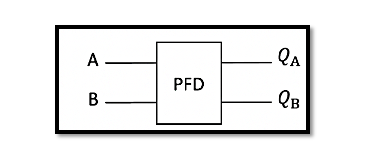
The PFD circuit typically consists of two D Flip-Flops (DFFs) and a reset mechanism. The circuit compares the rising edges of the input signals and generates outputs 𝑄𝐴 and 𝑄𝐵 accordingly. These outputs provide information about the phase and frequency difference between the signals.

Circuit Explanation:
- Inputs A and B: Two input signals with frequencies 𝑊𝐴WA and 𝑊𝐵WB.
- D Flip-Flops (1-DFF and 2-DFF): Triggered by the input signals, generating outputs 𝑄𝐴 and 𝑄𝐵.
- Reset Mechanism: Ensures the flip-flops are reset once the comparison is complete.
Output Waveforms:
- When 𝑊𝐴≠𝑊𝐵, the outputs 𝑄𝐴 and 𝑄𝐵 indicate the frequency difference.
- When 𝑊𝐴=𝑊𝐵, the outputs represent the phase difference.
This dual output capability makes PFDs effective in providing reliable information across a wide range of input conditions.
Take our entry level course (Below) for free using coupon code RAHRF101BLOG
RF Fundamentals, Basic Concepts and Components – RAHRF101
For limited time take an additional 10% off of all our courses using coupon code RFCERT10
Rahsoft RF Certificate and courses
Conclusion
Incorporating Phase/Frequency Detectors (PFDs) into Type-II PLLs significantly enhances their acquisition range and reliability. By addressing both frequency and phase differences, PFDs offer a more comprehensive solution compared to traditional phase detectors. This advancement is crucial for improving the performance of PLLs in various communication and signal processing applications.
Understanding and implementing PFDs can lead to more robust and efficient PLL designs, paving the way for better synchronization and stability in modern electronic systems.

Learn more about this topic by taking the complete course ‘Phase Lock Loop System Design Theory and Principles RAHRF469’. Watch the course videos for more detailed understanding. Also checkout other courses on RF system and IC design on https://rahsoft.com/courses/. Rahsoft also provides a certificate on Radio Frequency. All the courses offer step by step approach.
Tag:PFD, Phase Locked Loop, PLL, Type-II


