Understanding Charge Pumps in Phase-Locked Loops (PLLs)
Introduction
Charge pumps are crucial components in the design of phase-locked loops (PLLs), a type of feedback control system used to synchronize an output signal with a reference signal. This blog will show the function and importance of charge pumps in PLLs, using insights from the provided slides.
What is a Charge Pump?
A charge pump is a kind of DC to DC converter that utilizes capacitors for energetic charge storage to either raise or lower voltage levels. In the context of PLLs, a charge pump plays a pivotal role in adjusting the voltage controlled oscillator (VCO) to maintain phase alignment with the reference signal.

Charge Pump in a PLL
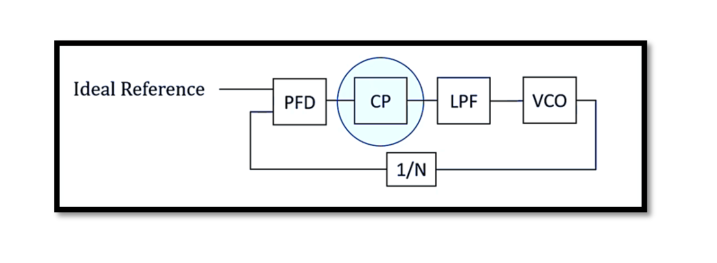
A typical PLL consists of several key components: a phase-frequency detector (PFD), a charge pump (CP), a low-pass filter (LPF), and a VCO, as shown in the first slide. The PFD compares the phase of the input signal with that of the feedback signal from the VCO, generating an error signal that indicates the phase difference. This error signal is then fed into the charge pump.

How Does a Charge Pump Work?
The charge pump, detailed in the second slide, switches between charging and discharging states. When the PFD detects a phase error, it sends pulses to the charge pump. Depending on the state of these pulses, the charge pump either charges or discharges a capacitor, thereby increasing or decreasing the control voltage (Vc).
- Charging: When the PFD outputs a signal indicating the VCO is lagging, the charge pump charges the capacitor, increasing Vc.
- Discharging: Conversely, if the VCO is leading, the charge pump discharges the capacitor, decreasing Vc.
This operation is depicted in the third slide, where the charging and discharging processes smooth out the pulses from the PFD, resulting in a more stable control voltage for the VCO.
The Role of the Low-Pass Filter
The low-pass filter (LPF) smooths out the ripples in the control voltage generated by the charge pump, ensuring a steady Vc is fed to the VCO. This is crucial for maintaining a stable frequency output.
VCO Control Voltage
The fourth slide illustrates what happens when the charge pump is connected to the VCO. As the control voltage (Vc) changes, it adjusts the frequency of the VCO. If there is a constant phase difference between the reference signal and the VCO signal, the charge pump will continuously adjust Vc until the PLL achieves lock, meaning the output frequency is synchronized with the reference frequency.

Locked PLL
In a type-II PLL, as depicted in the first additional slide, the input pulses must overlap to prevent the charge pump output from rising to infinite voltage. When the PLL is locked, the phase detector outputs are stable and the charge pump’s output current is zero, maintaining a constant control voltage 𝑉𝑐=𝑣1. This state ensures the VCO operates at a stable frequency that matches the reference signal.

Type-II PLL Loop
The second additional slide provides a detailed circuit diagram of a type-II PLL loop. In this configuration, the PFD uses flip-flops to detect phase differences and control the charge pump accordingly. The charge pump’s output is then filtered and fed to the VCO. This setup allows for more precise control over the VCO frequency, as the type-II PLL can correct both phase and frequency errors, providing greater stability and performance in applications requiring high precision.
Take our entry level course (Below) for free using coupon code RAHRF101BLOG
RF Fundamentals, Basic Concepts and Components – RAHRF101
For limited time take an additional 10% off of all our courses using coupon code RFCERT10
Rahsoft RF Certificate and courses
Conclusion
Charge pumps are integral to the operation of PLLs, ensuring precise control over the VCO and maintaining synchronization with the reference signal. By efficiently managing the charging and discharging of capacitors, charge pumps help stabilize the control voltage, thereby ensuring the PLL functions effectively. Understanding the nuances of charge pump operation, especially in type-II PLLs, can significantly aid in designing more efficient and robust PLLs for various applications. The inclusion of type-II PLLs demonstrates the advanced control capabilities necessary for modern electronic systems, highlighting the critical role of charge pumps in achieving accurate and stable frequency synthesis.

Learn more about this topic by taking the complete course ‘Phase Lock Loop System Design Theory and Principles RAHRF469’. Watch the course videos for more detailed understanding. Also checkout other courses on RF system and IC design on https://rahsoft.com/courses/. Rahsoft also provides a certificate on Radio Frequency. All the courses offer step by step approach.
Tag:Charge Pump, Phase Locked Loop, PLL, Type-II


