Understanding Charge Pump Phase-Locked Loop (CPPLL) Transfer Function
In this blog post, we will look into the details of the Charge Pump Phase-Locked Loop (CPPLL) transfer function, covering various aspects such as loop locking, charge pump behavior, and circuit analysis. This comprehensive discussion aims to provide a clear understanding of the CPPLL, essential for designing robust PLLs in electronic systems.
Loop Locking in CPPLL
The CPPLL system locks when the phase difference (Δϕ) between the input and output signals drops to zero. At this point, the charge pump remains relatively idle, indicating that the loop has achieved synchronization. This locking condition is crucial for maintaining the stability of the system. When there is a nonzero phase difference, the charge pump continuously builds up charge on the capacitor Cp, which affects the control voltage (Vcont). For the loop to remain locked and Vcont to be finite, the phase error must be zero. This behavior is distinct from Type I PLLs, where a steady-state phase error might be present.
Summary:
- Locking Condition: The loop locks when the phase difference (Δϕ) between the input and output signals drops to zero, causing the charge pump to remain relatively idle.
- Charge Build-Up: A nonzero phase difference leads to a continuous charge build-up on the capacitor Cp, affecting the control voltage (Vcont).
- Zero Phase Error: For the loop to lock and maintain a finite Vcont, the phase error must be zero. This behavior contrasts with Type I PLLs where a steady-state phase error might exist.
Transfer Function Analysis
The relationship between current and voltage in the CPPLL can be expressed as:

Here, ic is the current through the capacitor, C1 is the capacitance, ΔVcont is the change in control voltage, and Δt0\Delta t_0Δt0 is the time difference. The time difference Δt0 can be calculated using:

This equation shows how the control voltage Vcont is influenced by the phase difference Δϕ0 and the input period Tin. Using an approximation, the control voltage can be expressed as:

This approximation helps simplify the analysis and understand how the control voltage evolves over time.
Laplace Transform and Integrator Behavior
To further analyze the CPPLL, we can use Laplace transforms. The differential equation governing the system is:

Applying the Laplace transform, we get

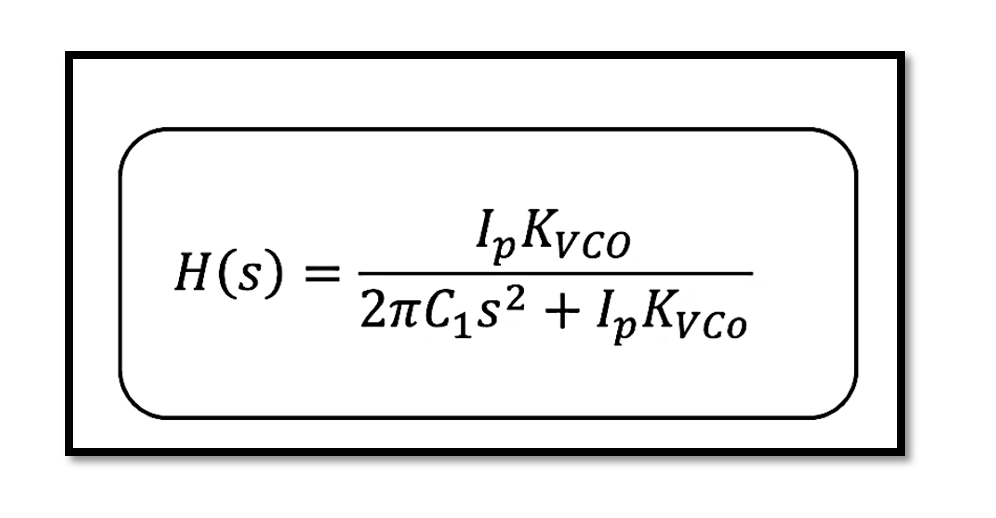
This shows that the control voltage Vcont is directly proportional to the phase difference in the Laplace domain. The transfer function of the system is then:

The CPPLL can be represented as an integrator in the Laplace domain, providing a continuous phase adjustment to achieve lock. The transfer function clearly illustrates how the control voltage is influenced by the phase difference, showcasing the integral action of the system.
Take our entry level course (Below) for free using coupon code RAHRF101BLOG
RF Fundamentals, Basic Concepts and Components – RAHRF101
For limited time take an additional 10% off of all our courses using coupon code RFCERT10
Rahsoft RF Certificate and courses
Simplified Method for Transfer Function
A simplified method to determine the CPPLL transfer function involves finding the impedance and multiplying it by the current source gain. The impedance Z1 of the capacitor C1 is given by:

This method confirms the earlier derived transfer function, providing a straightforward approach to understanding the relationship between control voltage and phase difference.
Conclusion
The Charge Pump Phase-Locked Loop (CPPLL) is a vital component in many electronic systems that require precise frequency and phase control. Understanding its transfer function is essential for designing robust PLLs. The CPPLL locks when the phase difference drops to zero, and any nonzero phase difference leads to a continuous charge build-up on the capacitor, affecting the control voltage. Through detailed circuit analysis and the use of Laplace transforms, we can derive the transfer function that shows the integral behavior of the system.

Learn more about this topic by taking the complete course ‘Phase Lock Loop System Design Theory and Principles RAHRF469’. Watch the course videos for more detailed understanding. Also checkout other courses on RF system and IC design on https://rahsoft.com/courses/. Rahsoft also provides a certificate on Radio Frequency. All the courses offer step by step approach.


