Understanding Higher Order Phase-Locked Loops (PLLs)
Why Do We Need Higher Order PLLs?
In the field of electronic circuit design, particularly within Phase-Locked Loops (PLLs), achieving optimal performance is crucial. PLLs are essential components in various applications such as communication systems, signal processing, and frequency synthesis. However, these systems often face challenges due to inherent non-ideal effects. One of the primary concerns is the presence of ripple in the control voltage (Vcontrol). This ripple, if not adequately addressed, leads to the generation of unwanted side bands, also known as spurs, at the output of the Voltage-Controlled Oscillator (VCO). Spurs can degrade the signal quality and performance of the PLL, making it imperative to suppress them effectively.
To mitigate these issues, higher order filters within PLLs become essential. These filters play a critical role in enhancing the stability and performance of the PLL by suppressing the Vcontrol ripple. Higher order filters, such as second-order or even higher, are designed to provide more stringent filtering characteristics compared to first-order filters. This additional complexity helps in reducing the ripple more effectively, thereby minimizing the spurs and ensuring cleaner output from the VCO.
Second Order Filter Design
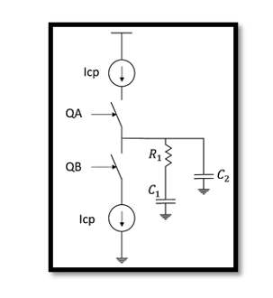
Designing a second-order filter for a PLL involves understanding its transfer function and the configuration of its components. The transfer function essentially defines how the filter processes the input signal to produce the desired output. For a second-order PLL, the open-loop transfer function can be expressed as:

In this equation:
- Icp represents the charge pump current, which is a critical component in determining the filter’s response.
- Kvco is the gain of the Voltage-Controlled Oscillator, influencing the overall loop gain.
- M is the division ratio, affecting the feedback within the PLL.
- R1, C1, and C2 are the filter components whose values determine the specific characteristics of the filter.
The term Cp is the parallel combination of C1 and C2, calculated as:

Additionally, wp3 represents the third pole frequency, which is given by:

This second-order filter introduces one zero and three poles into the system, which are essential for achieving the desired filtering characteristics.
Graphical Representation
The behavior of the second-order PLL filter can be better understood through its graphical representation, typically depicted using a Bode plot. A Bode plot displays the frequency response of the filter, showing how the magnitude and phase of the output signal vary with frequency. The magnitude plot indicates the gain of the system at different frequencies, while the phase plot reveals the phase shift introduced by the filter.

Key frequencies to note in the Bode plot include:
- wp3: The frequency at which the third pole is located, which significantly impacts the high-frequency behavior of the filter.
- wz: The frequency corresponding to the zero, which affects the low-frequency response.
- wu: The unity gain bandwidth frequency, a crucial parameter for determining the overall loop stability.
By analyzing the Bode plot, engineers can visualize how the filter behaves across different frequencies, allowing them to make informed decisions about component values and overall filter design.
Stability Considerations
Stability is a paramount concern in PLL design. From the Bode plot, it is evident that the placement of the third pole (wp3) plays a crucial role in maintaining stability. To ensure stable operation, the third pole should be positioned beyond the unity gain frequency (wu). This placement ensures that the unity gain frequency remains unaffected by the value of C2, allowing the use of previously determined values for critical parameters such as the unity gain frequency (wu), damping factor (ζ), and natural frequency (wn).
The phase margin (PM) is a measure of the system’s stability and is calculated as follows:

A higher phase margin indicates a more stable system. By carefully selecting the filter components and ensuring the third pole is appropriately placed, designers can achieve the desired phase margin, thereby ensuring the PLL operates stably under various conditions.
How to Choose C2?
Selecting the appropriate value for C2 is crucial for maintaining the desired phase margin and overall system performance. The term tan−1(wu/wp3) indicates how much the phase margin is degraded due to the placement of the third pole. To minimize this degradation, the value of C2 should be carefully chosen.

This example demonstrates that increasing wu/wz does not necessarily improve the phase margin. Instead, it is more effective to ensure that C2 is less than 0.2C1.
Take our entry level course (Below) for free using coupon code RAHRF101BLOG
RF Fundamentals, Basic Concepts and Components – RAHRF101
For limited time take an additional 10% off of all our courses using coupon code RFCERT10
Rahsoft RF Certificate and courses
Conclusion
In conclusion, higher order Phase-Locked Loops (PLLs) are essential for addressing non-ideal effects within PLL circuits, particularly in suppressing Vcontrol ripple. By employing higher order filters, such as second-order filters, engineers can significantly enhance the stability and performance of PLLs. Understanding the design principles, including the configuration of filter components and the placement of critical poles and zeros, is crucial for achieving optimal performance.
Through careful analysis and design, including the use of graphical representations like Bode plots, designers can ensure that PLLs operate stably and effectively, even under challenging conditions. Selecting appropriate component values, particularly for C2, is key to maintaining a desired phase margin and ensuring the overall success of the PLL design. By paying attention to these details and employing higher order filters, engineers can create robust PLL systems that meet the stringent requirements of modern electronic applications, ensuring reliable and high-quality performance.

Learn more about this topic by taking the complete course ‘Phase Lock Loop System Design Theory and Principles RAHRF469’. Watch the course videos for more detailed understanding. Also checkout other courses on RF system and IC design on https://rahsoft.com/courses/. Rahsoft also provides a certificate on Radio Frequency. All the courses offer step by step approach.


