Understanding RF Power Amplifiers
What is a Power Amplifier?
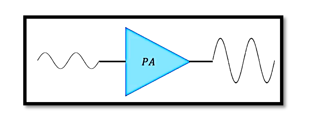
A power amplifier (PA) is a crucial component in various electronic systems, especially in communication devices. It amplifies the power of a signal, making it stronger and more suitable for transmission over long distances or through mediums that would otherwise attenuate the signal.
RF Power Amplifier
A Radio Frequency (RF) Power Amplifier is a type of amplifier specifically designed to amplify high-frequency signals used in radio communications. These amplifiers are tuned to work within specific frequency ranges and are essential for transmitting data over radio waves.
Role and Design Goals of RF Power Amplifiers
Typically, RF power amplifiers drive the antenna of a transmitter. The design goals of RF power amplifiers often include:
Power Gain: The ratio of output power to input power. It is a critical parameter that determines how much an amplifier boosts the signal.

Output Power: The maximum power the amplifier can deliver to the load. This is often specified in watts (W).
Bandwidth: The range of frequencies over which the amplifier can operate effectively. It is crucial for ensuring that the amplifier can handle the desired range of signals.
Power Efficiency: The ratio of the RF output power to the total DC power consumed. High efficiency is desired to minimize energy loss and heat generation.

Linearity: Ensures that the output signal is a linear amplification of the input signal, minimizing distortion.
Input and Output Impedance Matching: Proper matching of input and output impedances to the source and load, respectively, to maximize power transfer and minimize reflections.
Heat Dissipation: Managing and dissipating the heat generated during amplification to prevent damage to the amplifier components.
Transmitter Block Diagram

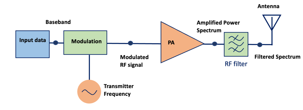
To understand the practical application of RF power amplifiers, it’s essential to look at a transmitter block diagram. This diagram illustrates the key components and their interactions in a typical RF transmitter.
Components of the Transmitter Block Diagram:
- Modulator: The modulator combines the information signal with the carrier signal. This process involves varying the carrier wave’s amplitude, frequency, or phase according to the information signal.
- Oscillator: The oscillator generates a continuous wave at the desired carrier frequency. This frequency is then modulated with the information signal.
- Mixer: The mixer combines the modulated signal with another frequency, typically generated by a local oscillator, to produce a signal at a new frequency (usually higher or lower). This process is known as frequency conversion.
- Filter: The filter removes unwanted frequencies from the mixed signal, ensuring that only the desired frequency components are passed to the next stage.
- Power Amplifier (PA): The RF power amplifier amplifies the filtered signal to a higher power level suitable for transmission. This stage is crucial for ensuring the signal can travel long distances without significant loss.
- Antenna: The antenna converts the amplified electrical signal into electromagnetic waves, which are then transmitted through the air.
Detailed Analysis of RF Power Amplifier Design
Power Gain: Power gain is a fundamental characteristic of an amplifier. It defines how much an amplifier can increase the power of a signal. In RF power amplifiers, power gain can be expressed as:

Output Power: The output power is the amplified power delivered to the load. It is typically measured in watts (W). High output power is necessary for transmitting signals over long distances or through obstacles.
Bandwidth: Bandwidth is the range of frequencies over which the amplifier can operate effectively. RF power amplifiers need to have a wide bandwidth to accommodate different channels and frequencies used in communication systems.
Power Efficiency: Efficiency is crucial for minimizing energy consumption and reducing heat generation. The power efficiency (η) of an amplifier can be defined as:

Linearity: Linearity ensures that the amplifier produces an output signal that is a linear reproduction of the input signal. Non-linearity can cause distortion and intermodulation, degrading the signal quality.
Impedance Matching: Proper impedance matching is essential for maximizing power transfer and minimizing signal reflections. The input impedance (Zin) of the amplifier should match the source impedance (ZS), and the output impedance should match the load impedance.

Mismatched impedances can lead to reflected signals and reduced power transfer efficiency.
Heat Dissipation: As RF power amplifiers handle high power levels, they generate significant heat. Efficient heat dissipation mechanisms, such as heat sinks and cooling systems, are necessary to prevent overheating and ensure reliable operation.
Practical Considerations In practical RF power amplifier design, engineers need to balance these parameters to achieve optimal performance. This often involves trade-offs, such as sacrificing some efficiency for higher linearity or increasing heat dissipation capabilities to handle higher output power.
Take our entry level course (Below) for free using coupon code RAHRF101BLOG
RF Fundamentals, Basic Concepts and Components – RAHRF101
For limited time take an additional 10% off of all our courses using coupon code RFCERT10
Rahsoft RF Certificate and courses
Conclusion
RF power amplifiers are indispensable in modern communication systems, enabling the transmission of signals over long distances and through challenging environments. Understanding the key parameters and design considerations is essential for developing efficient and reliable RF power amplifiers. By focusing on power gain, output power, bandwidth, efficiency, linearity, impedance matching, and heat dissipation, engineers can create amplifiers that meet the demanding requirements of today’s wireless communication networks.

Learn more about this topic by taking the complete course ‘Linear RF Power Amplifier (PA) Design Theory and Principles online course – RAHRF562’. Watch the course videos for more detailed understanding. Also checkout other courses on RF system and IC design on https://rahsoft.com/courses/. Rahsoft also provides a certificate on Radio Frequency. All the courses offer step by step approach.


