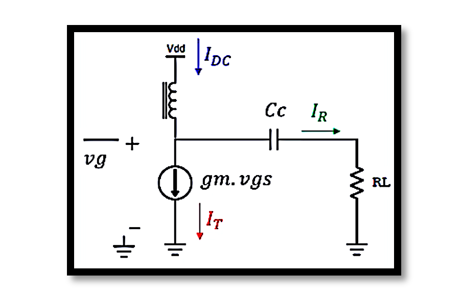
Understanding Basic Power Amplifier over one cycle of operation
Power amplifiers are essential components in various electronic devices, amplifying weak signals to drive larger loads such as speakers, RF transmitters, and other high-power devices. This blog will explore the fundamental operation of a basic power amplifier over one cycle, detailing the key concepts, components, and equations involved.
Introduction to Power Amplifiers
A power amplifier’s primary function is to increase the power level of an input signal without significantly distorting its waveform. The amplifier must deliver the required power to the load while maintaining efficiency and minimizing losses.
Transistor Operation in Power Amplifiers
Power amplifiers commonly use transistors as the active amplifying elements. The transistor’s operation can be understood by examining the input (gate) and output (drain) voltages and currents.
Basic Circuit Configuration
A typical power amplifier circuit includes:
- A transistor (e.g., MOSFET)
- Biasing components to set the operating point
- Coupling capacitors to isolate DC components
- Load resistor RL
Key Concepts and Equations
Instantaneous and Average Power
Power dissipation in the device (transistor) and power delivered to the load are critical parameters. The instantaneous power dissipated Pdiss(t) and the instantaneous power generated Pgen(t) can be expressed as:

Average Power
The average power dissipation over one cycle Pdiss and the average power generated Pgen are given by:


Transistor Operation Details
Biasing and Signal Components
The transistor in the amplifier circuit operates with a combination of DC bias and AC signal components. The biasing ensures that the transistor operates in the desired region of its characteristic curves, typically the active region for linear amplification.
The total current IT through the transistor is the sum of the DC bias current IDC and the AC signal current IR:


Voltage and Current Waveforms
The voltage and current waveforms at different points in the circuit provide insight into the amplifier’s operation. The gate voltage Vg, the total current IT, and the drain voltage Vd are critical for analyzing performance.
Power Dissipation and Generation Analysis
The power dissipation and generation can be visualized through the waveforms of Vd and IT.
Dissipated Power
The dissipated power in the device is represented by the shaded area in the waveform of IT and Vd. The instantaneous power dissipation is higher when both the current and voltage are high.
Generated Power
The generated power, delivered to the load, is represented by the red shaded area in the waveform of Vd − Vdc and IT – Idc. This represents the effective power that drives the load.
Practical Considerations
In designing and operating power amplifiers, several practical considerations must be addressed:
- Thermal Management: Efficient heat dissipation methods such as heat sinks are crucial to prevent overheating.
- Efficiency: Maximizing efficiency reduces power loss and improves performance. Class A, B, AB, and D amplifiers have different efficiency characteristics.
- Distortion: Minimizing distortion ensures signal integrity. Non-linearities in the transistor operation can lead to harmonic distortion.
Example Calculation
Consider a power amplifier with the following parameters:

The average power dissipation and generation can be calculated using the provided equations:

Take our entry level course (Below) for free using coupon code RAHRF101BLOG
RF Fundamentals, Basic Concepts and Components – RAHRF101
For limited time take an additional 10% off of all our courses using coupon code RFCERT10
Rahsoft RF Certificate and courses
Conclusion
Power amplifiers play a crucial role in amplifying signals for various applications. Understanding the operation over one cycle, including power dissipation and generation, is essential for designing efficient and reliable amplifiers. By analyzing the waveforms and using the relevant equations, engineers can optimize amplifier performance and address practical challenges such as thermal management and distortion.
Equations Summary


Learn more about this topic by taking the complete course ‘Linear RF Power Amplifier (PA) Design Theory and Principles online course – RAHRF562’. Watch the course videos for more detailed understanding. Also checkout other courses on RF system and IC design on https://rahsoft.com/courses/. Rahsoft also provides a certificate on Radio Frequency. All the courses offer step by step approach.
Tag:PA, POwer Amplifier, Transistor


