Load Line for Power Amplifiers
Introduction to Load Line Concept
The load line concept is crucial in understanding the behavior of electronic devices such as transistors when used in amplifiers. The load line represents the constraints imposed by the external circuit on the operation of the device. This blog will delve into the load line analysis with a focus on power amplifiers, exploring both ideal and real devices.
Real vs. Ideal Devices
Real Device Characteristics:
- The current-voltage characteristics of a real CMOS device exhibit a curved relationship between the drain current (ID) and the drain-source voltage (VDS).
- The graph shows multiple curves for different gate-source voltages (VGS), where each curve demonstrates an initial linear region followed by a saturation region.
Ideal Device Characteristics:
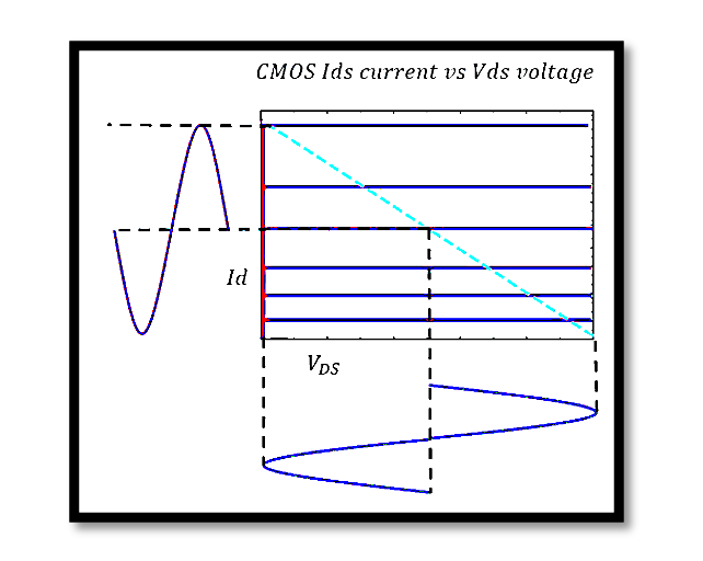
- For an ideal CMOS device, the ID vs. VDS plot shows flat, horizontal lines indicating that the current is independent of the voltage once the device is turned on.
- This simplification helps in theoretical analysis and design.

Understanding Load Line Analysis
Load line analysis helps in determining the operating point of the device, known as the Q-point, which is essential for ensuring that the amplifier operates correctly within its limits.
Load Line Equation:


Key Regions in the Load Line
Linear Region:
- In this region, the device behaves like a variable resistor. The current increases linearly with voltage.
Saturation Region:
- Here, the current remains relatively constant regardless of increases in VDS. This is crucial for amplifier operation to ensure linear amplification.
Example Calculation

Step-by-Step Calculation:


Redrawing Load Line:
- The load line can be plotted using the above equations and understanding the regions of operation. The intersection points with the device characteristics define the operating Q-point.
Recalculation with Given Ro
If the transistor has an output resistance Ro=200Ω

Take our entry level course (Below) for free using coupon code RAHRF101BLOG
RF Fundamentals, Basic Concepts and Components – RAHRF101
For limited time take an additional 10% off of all our courses using coupon code RFCERT10
Rahsoft RF Certificate and courses
Conclusion
The load line analysis is a fundamental tool in the design and understanding of power amplifiers. It ensures that the device operates within its safe and efficient regions. By understanding both the ideal and real characteristics of devices, engineers can design robust and efficient amplifiers.

Learn more about this topic by taking the complete course ‘Linear RF Power Amplifier (PA) Design Theory and Principles online course – RAHRF562’. Watch the course videos for more detailed understanding. Also checkout other courses on RF system and IC design on https://rahsoft.com/courses/. Rahsoft also provides a certificate on Radio Frequency. All the courses offer step by step approach.
Tag:Loadline, POwer Amplifier


