Optimum Load for Power Amplifiers: Maximizing Efficiency and Power Transfer
When designing power amplifiers, one of the most critical aspects is ensuring that the maximum amount of power is delivered to the load. This involves precise impedance matching and an understanding of both theoretical principles and practical constraints. This blog delves into the intricacies of optimum load for power amplifiers, providing a detailed explanation of how to achieve maximum power transfer and addressing the physical limitations that must be considered.
The Maximum Power Transfer Theorem
The foundation of optimizing load for power amplifiers lies in the Maximum Power Transfer Theorem. This theorem states that a generator delivers the maximum power to an external load when the load resistance is equal to the real part of the generator’s impedance. Mathematically, if a generator has an impedance Z0=R0+jX0, the load impedance Zin should be the complex conjugate of the generator’s impedance, Zin=R0+jX0, to achieve maximum power transfer. This condition is known as conjugate matching.

Impedance Matching
Impedance matching is crucial in minimizing reflections and ensuring that the maximum amount of power is transferred to the load. In practical terms, this means that the load resistance RL should be set equal to the real part of the generator’s impedance R0, and any reactive components should be resonated out. This can be represented as:

When these conditions are met, the power transfer is maximized, and the system is said to be optimally matched.
Physical Limitations: Current and Voltage Constraints
While the theoretical approach to achieving maximum power transfer is straightforward, real-world implementations must consider the physical limitations of the generator and the load. Specifically, there are constraints related to the maximum current the generator can supply and the maximum voltage it can sustain across its terminals.

Voltage Limits
One significant limitation is the maximum voltage that the generator can handle. For example, in a 180nm CMOS process, the maximum drain voltage Vdmax is typically around 2V. Exceeding this voltage can lead to breakdown issues, which can permanently damage the device. For GaAs processes, the maximum voltage is usually higher, but similar constraints apply.
Current Limits
Another crucial factor is the maximum current the generator can supply. High current levels can lead to electro-migration due to metal current density limitations. This phenomenon occurs when the high current causes the migration of metal atoms, which can eventually lead to circuit failure. Therefore, it’s essential to ensure that the current does not exceed the safe operational limits of the device.
Practical Example: Balancing Power and Constraints
To illustrate how to achieve optimal load while considering physical constraints, let’s go through a practical example.
Given Parameters
Suppose we have a generator with the following parameters:
- Current (I) = 1A
- Real part of impedance (R0) = 100 ohms

Assuming conjugate matching, the load resistance (RL) should also be 100 ohms. Under these conditions, the delivered power (P) can be calculated as:

However, this setup results in a drain voltage amplitude of:

This voltage is significantly higher than the safe operational limit for most devices.
Adjusting for Safe Operation
To bring the system within safe operational limits, adjustments can be made to the current and load resistance. For instance, if we increase the current to 2A and decrease the load resistance to 10 ohms, the new conditions are:

This voltage is within a safer range. The new delivered power is:

Graphical Analysis: Load Lines and Optimum Operating Points
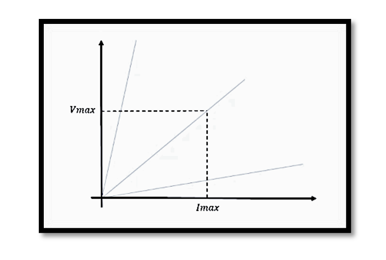
Graphical analysis using load lines can provide a visual representation of the relationship between voltage and current for different loads. By plotting Vmax against Imax, we can determine the optimum operating point that maximizes power transfer without exceeding device limits.
Optimum Load Graph
Consider a graph where the x-axis represents Imax and the y-axis represents Vmax. The slope of the line, given by Vmax/Imax, indicates the load resistance. The optimum load line is the one where the product Vmax⋅ Imax is maximized, ensuring maximum power transfer within the constraints of the device.

Detailed Optimum Load Analysis
To further illustrate, let’s consider another example:

The slope of the line is given by:

The maximum power can be calculated as:

Using these values, we can determine the optimum load resistance (Ropt) and ensure that the system operates within safe voltage and current limits.
Take our entry level course (Below) for free using coupon code RAHRF101BLOG
RF Fundamentals, Basic Concepts and Components – RAHRF101
For limited time take an additional 10% off of all our courses using coupon code RFCERT10
Rahsoft RF Certificate and courses
Conclusion
Optimizing the load for power amplifiers involves a delicate balance between theoretical principles and practical constraints. By ensuring proper impedance matching and considering physical limitations such as maximum current and voltage, we can achieve maximum power transfer while protecting the device from damage. Graphical analysis and practical examples illustrate how to adjust parameters to find the optimal operating point, providing a comprehensive approach to power amplifier design. Understanding these principles is essential for designing efficient and reliable power amplifiers in various applications.

Learn more about this topic by taking the complete course ‘Linear RF Power Amplifier (PA) Design Theory and Principles online course – RAHRF562’. Watch the course videos for more detailed understanding. Also checkout other courses on RF system and IC design on https://rahsoft.com/courses/. Rahsoft also provides a certificate on Radio Frequency. All the courses offer step by step approach.


