Current and Voltage Equations for All Amplifier Classes
In the design of electronic amplifiers, the classification of amplifiers based on their conduction angle, current, and voltage relationships is crucial for understanding their behavior, efficiency, and application. Amplifiers are commonly categorized into classes such as Class A, B, AB, and C, each with distinct characteristics in terms of their operation and efficiency. This blog delves into the detailed current and voltage equations governing these amplifier classes, providing a comprehensive understanding of their underlying principles.
Introduction to Amplifier Classes
Amplifier classes are defined primarily based on the conduction angle (α\alphaα) of the input signal, which is the portion of the input signal cycle during which the amplifier conducts current. The conduction angle directly influences the amplifier’s efficiency, linearity, and power dissipation. Let’s explore the current and voltage equations that describe the operation of different amplifier classes.
General Current Equation:
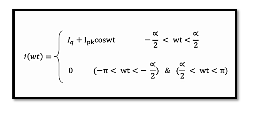
The general expression for the current i(wt) as a function of angular frequency wt is given by:

In Class A amplifiers, Iq=IDC, where IDC is the DC component of the drain current. For other classes, Iq≠ IDC
Boundary Conditions and Conduction Angle:
For different values of wt:

DC and Fundamental Components:
The DC component IDC of the current can be derived from the integral of i(wt) over one cycle:

Efficiency Calculations:
Efficiency is a critical parameter in amplifier design, especially in high-power applications. Two main types of efficiency are considered:
Output Efficiency (μ) is defined as:

Power Added Efficiency (PAE) accounts for the drive power Pin and is given by:

In terms of power delivered to the load Pout, efficiency can be re-expressed as: Where Pdiss is the power dissipated in the amplifier.

Power and Efficiency Considerations:
The relationship between the generated power and the delivered power to the load is critical for understanding the efficiency. The generated power is given by:
Generated power = −Delivered power to the Load = Pout
This relationship emphasizes that the efficiency is maximized when the power delivered to the load is maximized and power dissipation is minimized. Read more about Power and Efficiency in Power Amplifiers
Take our entry level course (Below) for free using coupon code RAHRF101BLOG
RF Fundamentals, Basic Concepts and Components – RAHRF101
For limited time take an additional 10% off of all our courses using coupon code RFCERT10
Rahsoft RF Certificate and courses
Concluding Remarks:
Understanding the current and voltage equations for different amplifier classes is crucial for optimizing amplifier design in terms of efficiency and performance. The detailed equations discussed here serve as foundational tools for engineers to analyze and design amplifiers that meet specific requirements for various applications. Whether optimizing for linearity, power efficiency, or specific operating conditions, these equations provide the necessary framework for making informed design decisions.

Learn more about this topic by taking the complete course ‘Linear RF Power Amplifier (PA) Design Theory and Principles online course – RAHRF562’. Watch the course videos for more detailed understanding. Also checkout other courses on RF system and IC design on https://rahsoft.com/courses/. Rahsoft also provides a certificate on Radio Frequency. All the courses offer step by step approach.


