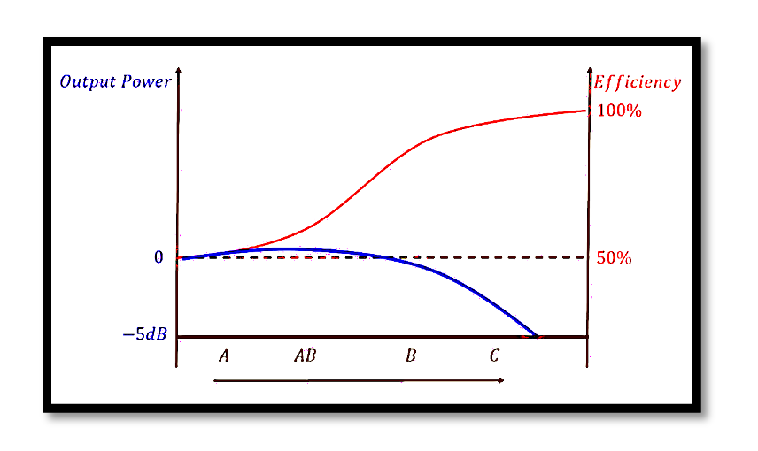
Comparison between different Power Amplifier Classes
Power amplifiers are categorized into different classes—Class A, Class B, Class AB, and Class C—each with distinct characteristics, efficiencies, and harmonics profiles. This blog delves into a technical comparison of these amplifier classes, providing a detailed analysis supported by equations, graphical representations, and key concepts. Understanding these differences is crucial for engineers and designers when selecting the appropriate amplifier class for a specific application.
Power Amplifier Classes Overview
Power amplifiers are generally classified based on their operation mode and conduction angle. The conduction angle refers to the portion of the input signal cycle during which the amplifier’s output device conducts. The primary classes of amplifiers include:
- Class A: The output device conducts for the entire 360° of the input signal.
- Class B: The output device conducts for exactly 180° of the input signal.
- Class AB: The output device conducts for more than 180° but less than 360° of the input signal.
- Class C: The output device conducts for less than 180° of the input signal.
Efficiency vs. Linearity
One of the most significant trade-offs in power amplifier design is between efficiency and linearity. Efficiency is the ratio of the RF output power to the total DC input power, while linearity indicates how accurately the amplifier reproduces the input signal without distortion. Class A amplifiers exhibit the lowest efficiency but the highest linearity, making them suitable for high-fidelity applications. On the other hand, Class C amplifiers boast the highest efficiency but at the cost of significant non-linearity and signal distortion.
Harmonic Content in Power Amplifiers
Harmonics are integer multiples of the fundamental frequency and are undesirable in most cases as they can cause distortion. Class B amplifiers, which operate in the linear region for only half the input cycle, introduce significant second harmonics. The harmonic content can be mathematically expressed as:

This equation shows how harmonics of different orders (3rd, 5th, etc.) contribute to the overall waveform distortion.
Power Gain and Input Drive
“If Class A and B have the same output power, what is the drawback of Class B?” The answer lies in the power gain and the required input drive.
To achieve the same output power as a Class A amplifier, a Class B amplifier requires a higher input drive. This is because Class B amplifiers operate over a smaller portion of the input signal, necessitating a greater swing in the input voltage to achieve the desired output. The graphical comparison shows that while Class A amplifiers require less input drive for the same output power, Class B amplifiers need a larger input voltage swing, reducing their overall power gain.

Equations and Technical Analysis
Let’s delve into the technical aspects of the different classes:
Class A Amplifiers:

Maximum efficiency typically around 25-30% due to continuous conduction of the output device.
Class B Amplifiers:

Harmonic content: Significant even harmonics due to the half-wave rectification nature of the operation.
Class AB Amplifiers:
Efficiency: Ranges between Class A and Class B, typically around 50-60%.
Harmonic content: Reduced compared to Class B but higher than Class A.
Class C Amplifiers:
Efficiency: η>80%, potentially approaching 100% in ideal cases. Harmonic content: Extremely high, with significant distortion making them suitable only for RF applications where the signal can be filtered.
Take our entry level course (Below) for free using coupon code RAHRF101BLOG
RF Fundamentals, Basic Concepts and Components – RAHRF101
For limited time take an additional 10% off of all our courses using coupon code RFCERT10
Rahsoft RF Certificate and courses
Practical Implications and Conclusion
Choosing the right amplifier class depends on the specific requirements of the application. For audio applications where fidelity is critical, Class A or Class AB amplifiers are preferable despite their lower efficiency. In contrast, for RF applications where efficiency is paramount and the signal can be filtered, Class C amplifiers are ideal. In summary, understanding the trade-offs between efficiency, linearity, harmonic distortion, and power gain is crucial in selecting the appropriate power amplifier class. The graphs and equations presented in this blog provide a clear and comprehensive comparison, aiding engineers in making informed decisions in amplifier design.

Learn more about this topic by taking the complete course ‘Linear RF Power Amplifier (PA) Design Theory and Principles online course – RAHRF562’. Watch the course videos for more detailed understanding. Also checkout other courses on RF system and IC design on https://rahsoft.com/courses/. Rahsoft also provides a certificate on Radio Frequency. All the courses offer step by step approach.


