Harmonic Trapping in Power Amplifier Load Networks
Introduction:
Harmonic distortion is a significant challenge in RF power amplifiers, especially those operating in Class AB, B, and C. These amplifiers are known for their efficiency and are widely used in various communication systems. However, the non-linearities inherent in these amplifiers produce harmonics that can degrade signal integrity and reduce power efficiency. To mitigate these issues, engineers employ harmonic trapping techniques within the load networks. This blog provides a detailed technical exploration of harmonic trapping, focusing on the design and implementation of LC tank circuits to suppress harmonics and optimize amplifier performance.
Understanding Harmonic Distortion in Class AB to C Amplifiers:
In Class AB to C amplifiers, the output current is non-sinusoidal due to the reduced conduction angle of the active device. This non-ideal current waveform contains harmonic components, which can be expressed using a Fourier series:

Here, ω0 is the angular frequency of the fundamental component, and I1,I2,I3,… represent the amplitudes of the fundamental and harmonic components. The second harmonic (I2) and higher-order harmonics are particularly problematic as they lead to power inefficiency, unwanted emissions, and signal distortion.
The Role of Harmonic Trapping:
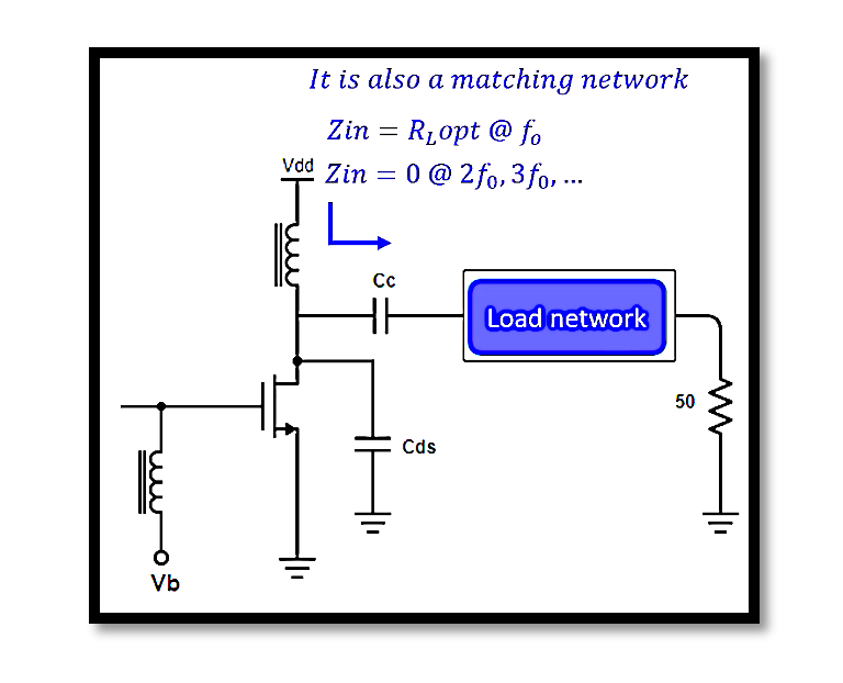
Harmonic trapping is a technique used to filter out these unwanted harmonics from the output signal. The goal is to ensure that the load network presents a high impedance at the fundamental frequency f0 while offering a low impedance path at harmonic frequencies (e.g., 2f0,3f0,etc.). This selective impedance control is typically achieved using LC tank circuits, which resonate at the fundamental frequency and suppress harmonics.
Design Principles of LC Tank Circuits for Harmonic Trapping:
The LC tank circuit is designed to resonate at a specific frequency, f0, where it presents maximum impedance. The resonance condition is defined by:

The key design objective is to choose L and C values that set the resonant frequency f0 to the desired operating frequency of the amplifier. At f0, the LC tank circuit presents a high impedance, allowing the fundamental component to pass through to the load while blocking the harmonic components.
Impedance Behavior of the LC Tank:
The impedance ZLC of the LC tank circuit is frequency-dependent and is given by:

At resonance ω0=2πf0, the reactive components cancel each other out, and the impedance is purely resistive and maximal. The behavior of the LC tank at harmonic frequencies is such that it presents a low impedance path, effectively shorting the harmonics and preventing them from reaching the load.
Quality Factor and Selectivity:
The quality factor Q of the LC tank circuit is a measure of its selectivity, defined as:

Where R is the equivalent series resistance of the inductor. A higher Q indicates sharper resonance, meaning the circuit is more selective at f0 and better at rejecting harmonics. The design of the LC tank should aim for a high Q to ensure effective harmonic trapping.
Practical Implementation of Harmonic Trapping:
In practical designs, the LC tank circuit is integrated into the load network as close to the transistor as possible to minimize parasitic effects. The total capacitance Ctot seen by the circuit includes both the external capacitor and the transistor’s intrinsic drain-source capacitance Cds. The inductance L and capacitance C must be carefully selected to ensure the tank circuit resonates precisely at the desired operating frequency.
Case Study: Harmonic Trapping in a Class B Power Amplifier:
Consider a Class B amplifier designed to operate at f0=900 MHz. The design steps for implementing harmonic trapping using an LC tank circuit are as follows:
Determine the Required Capacitance and Inductance:
- Assuming the total capacitance Ctot=10 pF, we can calculate the required inductance L to resonate at f0=900 MHz.
- The required inductance is given by:

Quality Factor Calculation:
- Assume the equivalent series resistance R is 1 Ω.
- The quality factor Q is:

- This indicates that the tank circuit has a moderate selectivity, sufficient for basic harmonic suppression.
Simulation and Verification:
- Use a simulation tool like ADS or LTSpice to model the LC tank circuit and analyze its impedance profile. The goal is to ensure that the impedance at f0 is high, and at 2f0 and 3f0, the impedance is sufficiently low to trap harmonics.
Testing and Tuning:
- Prototype the circuit and measure the actual impedance at different frequencies. Adjust L and C values if necessary to fine-tune the resonant frequency and improve harmonic suppression.
Implications for Power Amplifier Performance:
Effective harmonic trapping using LC tank circuits significantly enhances the performance of Class AB to C power amplifiers. By minimizing harmonic content, the amplifier operates more efficiently, with less distortion and improved signal quality. Additionally, the reduced harmonic emissions ensure compliance with regulatory standards and minimize interference with other communication systems.
Take our entry level course (Below) for free using coupon code RAHRF101BLOG
RF Fundamentals, Basic Concepts and Components – RAHRF101
For limited time take an additional 10% off of all our courses using coupon code RFCERT10
Rahsoft RF Certificate and courses
Conclusion:
Harmonic trapping is a critical technique in the design of load networks for RF power amplifiers, particularly in Class AB to C configurations. The use of LC tank circuits allows engineers to selectively suppress unwanted harmonics while maintaining optimal power transfer at the fundamental frequency. Through careful design, simulation, and testing, these circuits can be fine-tuned to meet the demanding requirements of modern RF systems, ensuring high efficiency and signal integrity.

Learn more about this topic by taking the complete course ‘Linear RF Power Amplifier (PA) Design Theory and Principles online course – RAHRF562’. Watch the course videos for more detailed understanding. Also checkout other courses on RF system and IC design on https://rahsoft.com/courses/. Rahsoft also provides a certificate on Radio Frequency. All the courses offer step by step approach.


