Load Tuning for Class AB to C Power Amplifiers
Introduction:
Load tuning networks are fundamental in achieving optimal performance in RF power amplifiers, especially those operating in Class AB, B, and C. These classes of amplifiers are widely used in communication systems due to their efficiency and ability to amplify signals with varying degrees of linearity and power output. However, designing load networks for these amplifiers is challenging due to the presence of significant harmonic content in the output current, especially at the second harmonic. This blog provides an in-depth technical exploration of load tuning techniques, focusing on harmonic suppression, impedance matching, and the use of LC tank circuits.
Understanding Load Tuning in Class AB to C Amplifiers:
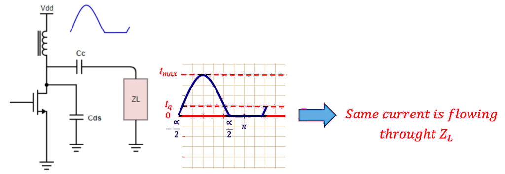
In Class AB to C amplifiers, the transistor operates with a conduction angle less than 360 degrees, which means that the current waveform is inherently non-sinusoidal. This non-linearity results in the generation of harmonics, which, if not properly managed, can lead to inefficient power transfer and signal distortion. The goal of load tuning is to ensure that the amplifier load is presented with an optimal impedance at the fundamental frequency while simultaneously suppressing the higher-order harmonics.

The Role of the Load Network:
The load network in a power amplifier serves multiple purposes:
- Impedance Matching: Ensuring that the load impedance is optimally matched to the output impedance of the amplifier, maximizing power transfer.
- Harmonic Suppression: Reducing the impact of harmonics on the output signal to maintain signal integrity and efficiency.
- Power Efficiency: Enhancing the overall efficiency of the amplifier by minimizing power loss due to reflected waves and harmonic content.
The design of the load network must therefore address these aspects simultaneously, which is typically achieved through the use of LC tank circuits.
Harmonic Content in Class AB to C Amplifiers:
The current waveform in a Class AB amplifier, for example, can be expressed as a Fourier series:

Where ω0 is the angular frequency of the fundamental component, and I1,I2,… are the amplitudes of the fundamental and harmonic components. The presence of I2I_2I2, the second harmonic, is particularly problematic because it contributes to distortion and can reduce the efficiency of power transfer to the load.

Designing the LC Tank Circuit for Harmonic Suppression:
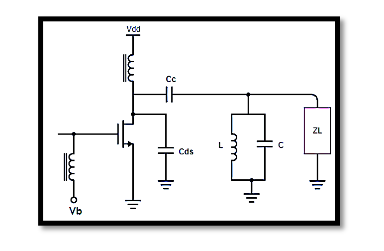
An LC tank circuit is typically used in the load network to suppress harmonics. The tank circuit is designed to resonate at the fundamental frequency f0, presenting a high impedance at f0 and a low impedance at harmonic frequencies (2f0, 3f0, etc.). The resonance condition is given by the standard equation:

Practical Considerations in LC Tank Design:
Quality Factor (Q): The quality factor Q of the LC circuit determines how selective the tank is at the fundamental frequency. It is defined as:

A higher Q means sharper selectivity, which is beneficial for isolating the fundamental frequency from harmonics.
Total Capacitance Ctot: The total capacitance in the tank circuit includes both the external capacitor and the intrinsic capacitance Cds of the transistor. The design must account for this to accurately tune the circuit to fo.
Impedance Transformation: The load network often needs to transform the load impedance RL to match the optimal impedance of the amplifier. This can be achieved using a combination of transformers and LC networks.
Parasitic Effects: Real-world components have parasitic inductances and capacitances that can shift the resonant frequency. Careful layout and component selection are necessary to minimize these effects.
Example: Harmonic Suppression in a Class B Amplifier
Consider a Class B amplifier designed to operate at a fundamental frequency fo=1GHz. The design process involves the following steps:
- Determine the Load Impedance RL: Assuming the optimal load impedance is 50Ω.
- Select the LC Components: Choose L and C such that the tank resonates at 1GHz.
- For example, L=1.59 nH and C=10 pF might be chosen, yielding fo≈1 GHz.
- Calculate the Quality Factor Q: With the chosen components, calculate Q to ensure sufficient selectivity.
- Analyze the Impedance: Use network analysis tools to verify that the impedance at fo is optimal and that at 2fo and 3fo, the impedance is sufficiently low to suppress harmonics.
Simulation and Testing:
Before implementing the design, it’s critical to simulate the load network using software tools like ADS or LTSpice. Simulation helps to visualize the impedance profile across frequencies and ensures that the design meets the required specifications. After simulation, prototype testing with actual components is performed to validate the design under real-world conditions.
Take our entry level course (Below) for free using coupon code RAHRF101BLOG
RF Fundamentals, Basic Concepts and Components – RAHRF101
For limited time take an additional 10% off of all our courses using coupon code RFCERT10
Rahsoft RF Certificate and courses
Conclusion:
Designing load tuning networks for Class AB to C amplifiers involves a careful balance of harmonic suppression, impedance matching, and power efficiency. The use of LC tank circuits is a proven technique for achieving these goals, enabling the amplifier to deliver clean, efficient power to the load. By carefully selecting and tuning the components, engineers can significantly enhance the performance of RF power amplifiers, making them suitable for demanding applications in modern communication systems.

Learn more about this topic by taking the complete course ‘Linear RF Power Amplifier (PA) Design Theory and Principles online course – RAHRF562’. Watch the course videos for more detailed understanding. Also checkout other courses on RF system and IC design on https://rahsoft.com/courses/. Rahsoft also provides a certificate on Radio Frequency. All the courses offer step by step approach.


