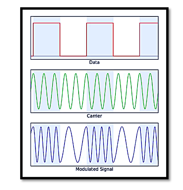
Frequency Shift Keying (FSK): Overview
Frequency Shift Keying (FSK) is a digital modulation scheme where the frequency of a carrier signal is changed based on the digital data (binary bit stream). It is a robust and simple technique often used in communication systems, especially in low-cost applications like telemetry, RF remote controls, and wireless data transmission.
In binary FSK, two distinct frequencies represent binary ‘1’ and ‘0’. These frequencies are referred to as f1 (mark frequency) and f2 (space frequency). FSK can involve more than two frequencies for higher-order systems, but in this explanation, we focus on binary FSK. The mathematical representation of the FSK signal can be given as:

The carrier frequency shifts between f1 and f2 depending on the binary input sequence.
FSK Modulation
The FSK modulator generates an FSK signal based on the input binary bit stream.

Key Components of FSK Modulator:
- Oscillators:
- Two oscillators generate the frequencies f1 and f2 corresponding to binary ‘0’ and ‘1’.
- The carrier wave for binary ‘0’ is Acos(ω1t+θ1), and for binary ‘1’, it is Acos(ω2t+θ2).
- Switching Circuit:
- The modulator uses a binary message to control a switch, determining which oscillator output is selected for transmission.
- If the input bit is ‘0’, the modulator selects the signal from oscillator #1 (f1).
- If the input bit is ‘1’, the modulator selects the signal from oscillator #2 (f2).
Working:
- The binary input data stream toggles the switch to alternate between the two oscillators, thereby producing a modulated waveform with f1 and f2 corresponding to binary ‘0’ and ‘1’.
FSK Demodulation

Demodulation is the process of retrieving the original binary data from the FSK-modulated signal. There are several methods for FSK demodulation, including Asynchronous and Synchronous Demodulation.
Asynchronous Demodulator:
The asynchronous demodulation technique does not require phase synchronization with the carrier signal.
Components:
- Bandpass Filters (BPF): Two filters are designed to separate f1 and f2 from the incoming FSK signal.
- BPF1 passes f1 (space frequency).
- BPF2 passes f2 (mark frequency).
- Envelope Detectors: These extract the amplitude variations corresponding to each frequency.
- Decision Circuit: It compares the outputs of the envelope detectors and decides the binary value based on the dominant frequency.
Working:
- The incoming FSK signal is passed through the bandpass filters, isolating f1 and f2.
- The envelope detectors process the filtered signals to produce DC voltages proportional to the presence of f1 and f2.
- The decision circuit compares these voltages to reconstruct the binary data.
Synchronous Demodulator:

Synchronous demodulation uses a locally generated reference signal that is synchronized with the carrier frequency.
Components:
- Mixers: Multiply the received signal with locally generated signals at f1 and f2.
- Bandpass Filters: Filter out unwanted frequency components, retaining only the signals of interest.
- Decision Circuit: Determines the binary value by comparing the filtered outputs.
Working:
- The received FSK signal is multiplied with Acos(ω1t) and Acos(ω2t) in separate branches.
- Bandpass filters retain the components at f1 and f2.
- The decision circuit evaluates the outputs to reconstruct the binary sequence.

Demodulation using Phase-Locked Loop (PLL)
A PLL-based demodulator is highly efficient and widely used for FSK demodulation.
Components:
- Phase Comparator: Compares the phase of the incoming FSK signal with the locally generated signal.
- Voltage-Controlled Oscillator (VCO): Generates a signal whose frequency is controlled by the output of the phase comparator.
- Low-Pass Filter: Filters out high-frequency components, retaining the DC voltage (error signal).
- Decision Circuit: Converts the DC voltage into binary data.
Working:
- The incoming FSK signal is fed into the PLL.
- The phase comparator generates an error voltage based on the frequency deviation of the input signal (f1 or f2).
- The VCO adjusts its frequency to match the incoming signal, locking onto either f1 or f2.
- The error voltage is interpreted by the decision circuit to determine the binary output.

Applications of FSK
- Wireless Communication: Used in low-power devices like garage openers and RFID systems.
- Telemetry: For transmitting sensor data over long distances.
- Data Modems: Early modems used FSK for encoding binary data.
- Digital Radio: FSK serves as the foundation for many digital radio standards.
Advantages and Limitations
Advantages:
- Simple implementation for binary data.
- Robust against noise compared to amplitude-based modulation schemes.
- Effective for low-bandwidth systems.
Limitations:
- Requires more bandwidth than amplitude or phase modulation.
- Limited data rate compared to higher-order modulation schemes.
Take our entry level course (Below) for free using coupon code RAHRF101BLOG
RF Fundamentals, Basic Concepts and Components – RAHRF101
For limited time take an additional 10% off of all our courses using coupon code RFCERT10
Rahsoft RF Certificate and courses
Conclusion
Frequency Shift Keying is a versatile modulation scheme with straightforward implementation and robust performance. FSK modulators rely on frequency oscillation and switching, while FSK demodulators employ techniques like asynchronous filtering, synchronous detection, or PLL for decoding the binary message. Its simplicity makes it a preferred choice for many practical applications, ranging from wireless communication to digital data transmission.

Learn more about this topic by taking the complete course ‘Introduction to Modulation in Communication Systems Online Course – RAHRF152’. Watch the course videos for more detailed understanding. Also checkout other courses on RF system and IC design on https://rahsoft.com/courses/. Rahsoft also provides a certificate on Radio Frequency. All the courses offer step by step approach.


