Serial-to-Parallel (S/P) Converter in Digital Communication Systems
Introduction
In digital communication and signal processing systems, the efficient handling of data transmission and processing is crucial for optimizing performance. One of the fundamental components that facilitate this efficiency is the Serial-to-Parallel (S/P) Converter. This device or algorithm is essential in various digital applications, such as digital modulation schemes (QPSK, QAM, and OFDM), microprocessor interfaces, and data storage systems. This blog provides a comprehensive technical analysis of the S/P converter, including its working principles, equations, block diagrams, and practical implementations.
Fundamentals of a Serial-to-Parallel Converter
What is a Serial-to-Parallel Converter?
A Serial-to-Parallel (S/P) Converter is a circuit that takes an incoming serial data stream and converts it into a parallel data format. Serial data transmission sends one bit at a time, which is useful for long-distance communication but is inefficient for processing. Converting serial data into parallel format increases data processing speed and is essential for high-speed digital systems.
Why is S/P Conversion Important?
- Increases Data Throughput: Parallel data transmission allows for simultaneous processing of multiple bits.
- Optimizes Digital Signal Processing (DSP): Many DSP and computing systems operate on parallel data.
- Efficient Use of Bandwidth: Helps in modulation schemes like QPSK and OFDM by grouping bits into symbols.
- Essential in High-Speed Interfaces: Used in PCIe, USB, and Ethernet data communication.
Working Principle of S/P Converter
The S/P conversion process follows a structured approach to convert sequential data into grouped parallel outputs.
Step-by-Step Process:
- Data Buffering: The serial data stream is received and stored in a shift register.
- Clock Synchronization: A clock signal ensures that bits are read in the correct sequence.
- Bit Segmentation: The bits are grouped into fixed lengths, typically 2-bit, 4-bit, or 8-bit.
- Latch Mechanism: Once the register is full, the data is latched into parallel output lines.
- Parallel Output Generation: The stored bits are then sent out simultaneously across multiple output lines.
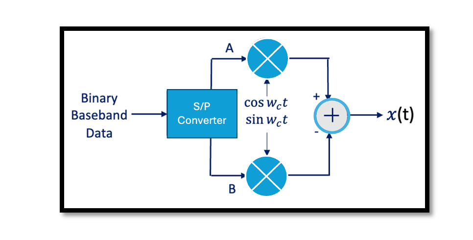
Below is a block diagram illustrating the operation of an S/P converter:
Mathematical Representation
The function of an S/P converter can be expressed mathematically as: Given a serial data stream S(t), where each bit is received at time t, the parallel output P(n,t) at time t is given by:
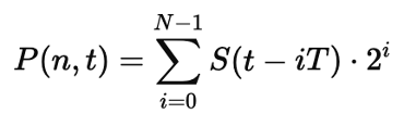
where:
- N is the number of parallel bits,
- T is the clock cycle duration,
- S(t) represents the incoming serial data stream,
- P(n,t) represents the parallelized data.
This equation highlights the conversion of serial bits into an N-bit parallel word by summing appropriately shifted binary values.
Applications of S/P Converters
S/P converters are widely used in various digital communication and processing systems. Below are key areas where they play a crucial role:
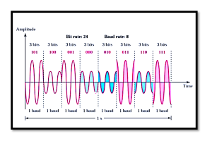
1. Digital Modulation Techniques (QPSK, QAM, OFDM)
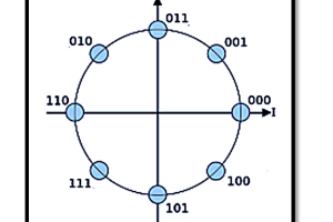
- In QPSK (Quadrature Phase Shift Keying), a serial bit stream is grouped into two-bit symbols before modulation.
- In QAM (Quadrature Amplitude Modulation), data symbols are formed using a higher-order parallel bit representation.
- In OFDM (Orthogonal Frequency Division Multiplexing), multiple subcarriers carry parallel data streams, requiring an S/P converter before transmission.
2. High-Speed Communication Interfaces (PCIe, USB, Ethernet)
- PCIe (Peripheral Component Interconnect Express) uses parallel data lanes for high-speed computing applications.
- USB (Universal Serial Bus) utilizes serial-to-parallel conversion internally to manage high-speed data transmission.
- Ethernet Communication converts received serial data into parallel format for efficient processing in network interfaces.
3. Microprocessors and Memory Systems
- Microprocessors communicate with external devices using serial interfaces, which are converted to parallel for internal bus operations.
- RAM (Random Access Memory) and SSDs (Solid-State Drives) operate with parallel data buses but interact with external components serially.
Advantages of S/P Conversion
- Enhanced Data Throughput – Converts slow serial streams into high-speed parallel processing.
- Lower Processing Latency – Parallel data transmission reduces delay cycles.
- Efficient Modulation & Transmission – Enables multi-bit symbol formation in digital modulation.
- Scalability for Higher Bit Rates – Allows seamless adaptation to higher bandwidth systems.
Implementation of S/P Converter
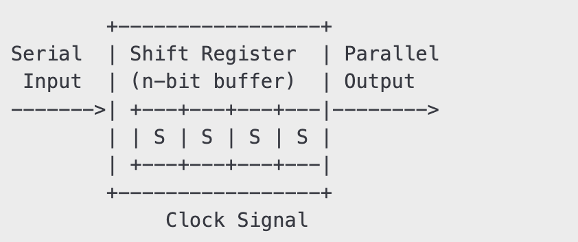
Hardware Implementation A typical hardware-based S/P converter consists of shift registers and D flip-flops, as shown below:

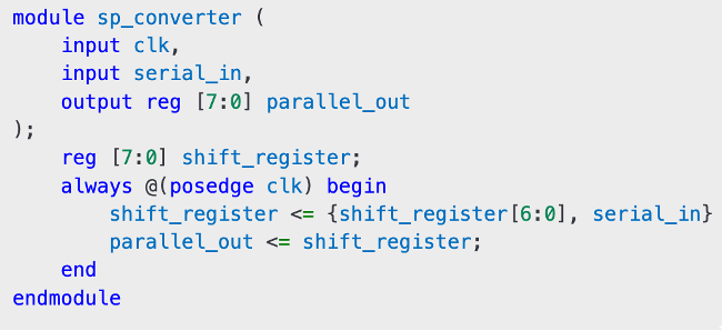
The shift register loads incoming serial bits at each clock pulse. Once the register is full, the latch holds the value, and the data is output in parallel. Modern S/P converters are implemented in Field Programmable Gate Arrays (FPGAs) and ASICs using VHDL or Verilog. A simple Verilog implementation:
Take our entry level course (Below) for free using coupon code RAHRF101BLOG
RF Fundamentals, Basic Concepts and Components – RAHRF101
For limited time take an additional 10% off of all our courses using coupon code RFCERT10
Rahsoft RF Certificate and courses
Conclusion
The Serial-to-Parallel (S/P) Converter is a crucial component in digital communication and processing systems. It enables efficient handling of high-speed data by converting slow serial inputs into parallel outputs. Its application spans various fields, including modulation techniques (QPSK, QAM, OFDM), high-speed communication interfaces (PCIe, USB, Ethernet), and microprocessor memory systems. With increasing demand for higher data rates and parallel processing, S/P converters continue to be essential in modern digital systems, offering optimized performance, reduced latency, and scalable architecture solutions.

Learn more about this topic by taking the complete course ‘Introduction to Modulation in Communication Systems Online Course – RAHRF152’. Watch the course videos for more detailed understanding. Also checkout other courses on RF system and IC design on https://rahsoft.com/courses/. Rahsoft also provides a certificate on Radio Frequency. All the courses offer step by step approach.
You may also like
Understanding Quadrature Amplitude Modulation (QAM) and Its Applications