I-Q Mismatch in Communication Systems
In modern communication systems, Quadrature Amplitude Modulation (QAM) and Quadrature Phase Shift Keying (QPSK) are extensively used for high-speed data transmission. These schemes rely on accurate in-phase (I) and quadrature (Q) signal components to encode information. However, real-world imperfections often lead to I-Q mismatch, a critical issue that degrades system performance.
I-Q mismatch arises due to imperfections in the hardware implementation of modulators, demodulators, or mixers. This article dives deep into the two main types of I-Q mismatch: amplitude mismatch and phase mismatch, their origins, and their impact on system performance.
What is I-Q Mismatch?
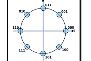
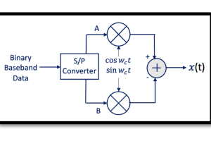
An ideal I-Q modulator generates two orthogonal components:
- I-component proportional to cos(ωt)
- Q-component proportional to sin(ωt)
In the ideal case, these components are perfectly balanced in amplitude and orthogonal in phase (90° apart). Any deviation from this ideal behavior causes:
- Amplitude mismatch: The I and Q components have unequal magnitudes.
- Phase mismatch: The phase difference between I and Q components deviates from 90°.
These mismatches are primarily due to circuit nonlinearities, manufacturing imperfections, or component tolerances in the transmitter or receiver chain.
Amplitude Mismatch
Origin and Mathematical Representation
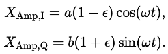
Amplitude mismatch occurs when the gain applied to the I and Q components differs. Let the amplitudes of the I and Q components be scaled by factors 1−ϵ and 1+ϵ respectively, where ϵ is the amplitude mismatch factor. The generalized I-Q signals can be represented as:
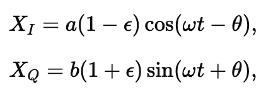
where a and b are ideal amplitude scaling factors, and θ accounts for phase offset (assumed zero for pure amplitude mismatch). When θ=0, the amplitudes of the I and Q components become:
Visualizing Amplitude Mismatch
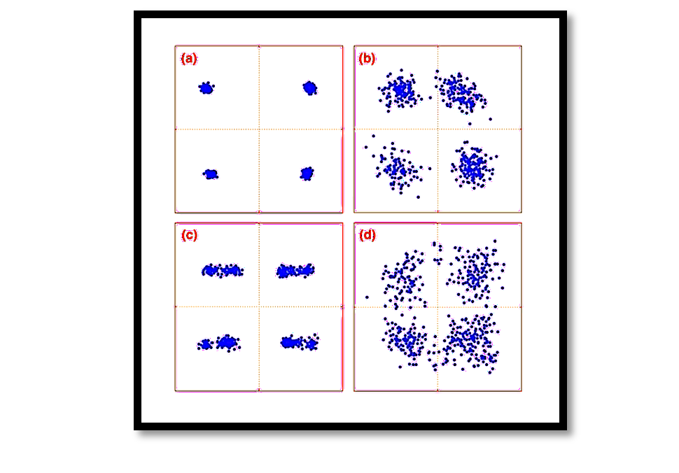
Amplitude mismatch distorts the ideal constellation diagram. For example:
- In QPSK, the constellation points, which ideally form a perfect square, are scaled unequally in the I and Q dimensions, leading to rectangular or skewed patterns.
- This distortion affects the detection of transmitted symbols and increases the bit error rate (BER).
Amplitude mismatch is often mitigated through calibration techniques in the hardware or software domain.
Phase Mismatch
Origin and Mathematical Representation
Phase mismatch occurs when the I and Q signals are no longer orthogonal, i.e., the phase difference between them deviates from 90°. Such a deviation is denoted by ϕ, the phase error. The modulated signal can be expressed as:
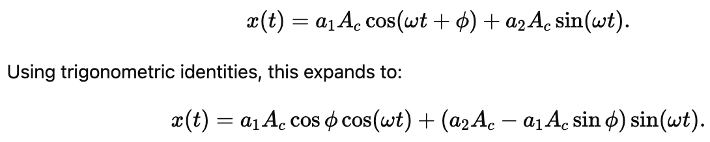
In this representation:
- The I-component (ION) and Q-component (QON) no longer align perfectly with the original axes.
- This leads to both amplitude and angular distortions in the transmitted signal.
Visualizing Phase Mismatch
Phase mismatch rotates the constellation diagram. For instance:
- In QPSK, the 90° separation between adjacent constellation points reduces, causing overlap or misinterpretation of symbols.
- The mismatch introduces inter-symbol interference (ISI) and degrades system performance.
Key Observations
- For small phase errors (ϕ≈0), the distortion is minimal but still impacts the error vector magnitude (EVM).
- For larger errors, the orthogonality of the system breaks down, making recovery of the transmitted signal significantly harder.
Combined Effects of Amplitude and Phase Mismatch
When both amplitude and phase mismatches occur simultaneously, the signal distortion becomes more pronounced:
- The constellation diagram exhibits both scaling and rotation.
- The transmitted power is inefficiently utilized, leading to higher error rates.
A general representation considering both amplitude mismatch (ϵ) and phase mismatch (ϕ) is:
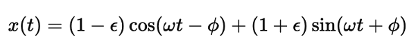
The combined impact can be visualized as a skewed and rotated constellation.
Mitigation Techniques
- Hardware Calibration:
- Use precision components to minimize variations.
- Implement automatic gain control (AGC) circuits to equalize the amplitudes.
- Digital Signal Processing (DSP):
- Apply adaptive algorithms to estimate and correct I-Q mismatch in real-time.
- Techniques like blind source separation (BSS) or least mean square (LMS) filters can effectively compensate for mismatches.
- Error Correction Codes:
- Use advanced coding schemes to tolerate increased noise and distortion.
- Regular Testing and Calibration:
Perform periodic testing of the communication chain to ensure performance remains within acceptable limits.
Take our entry level course (Below) for free using coupon code RAHRF101BLOG
RF Fundamentals, Basic Concepts and Components – RAHRF101
For limited time take an additional 10% off of all our courses using coupon code RFCERT10
Rahsoft RF Certificate and courses
Conclusion
I-Q mismatch is a fundamental issue in modern communication systems that arises due to imperfections in hardware components. While amplitude and phase mismatches affect system performance differently, their combined effect can significantly degrade signal quality. Understanding these mismatches and implementing effective mitigation strategies is crucial for designing robust communication systems. Through advancements in DSP and calibration techniques, many of these issues can be addressed, ensuring reliable and high-performance signal transmission even in non-ideal conditions.

Learn more about this topic by taking the complete course ‘Introduction to Modulation in Communication Systems Online Course – RAHRF152’. Watch the course videos for more detailed understanding. Also checkout other courses on RF system and IC design on https://rahsoft.com/courses/. Rahsoft also provides a certificate on Radio Frequency. All the courses offer step by step approach.
You may also like
Understanding Quadrature Amplitude Modulation (QAM) and Its Applications