Non-linearity and its effects in RF System
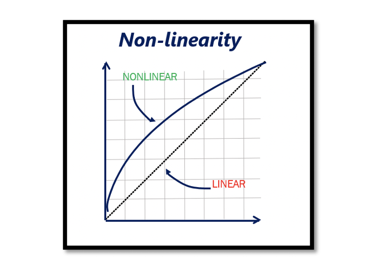
Linearity: Linearity is the property of a mathematical relationship or function, which can be graphically represented as a straight line. Linearity can be graphically represented as a straight line. We always expect to have this kind of outputs in our systems but actually in the real world it is bit hard and challenging to have a completely linear system, we end up having non-linearity.
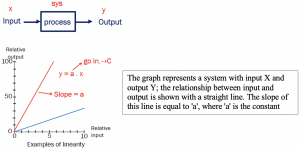
For example we have a system and the process here is amplification. The input to the amplifier is ‘x’ and output is ‘y’, we can graphically represent the relationship for x & y. For linear amplifier the relationship between x & y can be shown with a straight line and the slope of this line is equal to ‘a’. Where ‘a’ is the coefficient or gain and it is constant. So the output y=a.x.
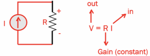
Another example of this system can be a resistor. In this circuit with input current ‘I’ and measuring the output voltage V across resistor ‘R,’ we will get V=R.I, where V is output, I is the input, and R is the constant gain. This resistor represents a linear system, and it has a linear behavior. output Y=a.X. However, it’s not quite true in real world because this resistance may change with temperature and due to temperature variations, this system will become non-linear. The two terms a2 and a3 in the below equation causes non-linearity.
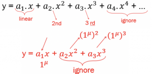
Non-linearity: In a non-linear system, as shown in equation (1), in addition to the first term we had in linear, there are two more terms called 2nd order non-linearity and 3rd order non-linearity. However, it is not limited to only two terms, and it can have more. As we proceed further, the terms after 3rd order become small and low for comparison; hence, they can be ignored sometimes. When the system is really sensitive, these terms are also taken into account.
In cases where the value of ‘x’ is very small, the 2nd order and 3rd order terms are also ignored. Hence the system for a very small value of ‘x’ is linear. If a system shows non-linear behavior, it means ‘x’ holds considerable value and is not very small.
Example 1:
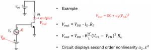
In this non-linear system example circuit, the input is Vgs, and the output is Vout, which is equal to VOUT= VDD-ID.RL. Read about the small signal analysis of the MOS transistor. The transistor in the circuit is working in saturation region with DC power considering AC is 0, then Vout can be further written as:
This circuit displays 2nd order non-linearity (a2.x2) and the relationship between input and output can be shown with a straight line. Vout shows a non-linear behavior in the equation: Vout=DC+a2.(VGS)2.
Example 2:
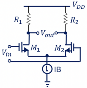
This example is of a MOS differential pair. The behaviour of this system is analysed using the given equations for differential pair. So, equation (3) shows the relationship between Vout and Vin in the given circuit.
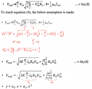
To reach equation (4), the few assumptions are made as shown. The condition is: b2 is much smaller than ‘a’ and considered 0 and using the approximation we get equation (4). This circuit is now behaving like the 3rd order non-linear system, and it doesn’t have a second-order term.

Making another assumption for this example circuit, the input Vin to the circuit is very small and is considered to be 0. This graph shows the curves for input voltage versus output current, and the intersection region Vin has a very small amplitude. Therefore, the term a3can be ignored, considering it to be 0. Now we reached the point where the Vout behaves like a normal transistor with the value a1 only. Also, we read in previous sections that Vout = gmRDVin.
When calculating the gain for our circuit in small-signal analysis, we always assume that our input has a low value like 1 micro volt for one stage for differential pair. But if you go and increase your value for Vin, the amplitude increases. In such a case, the system won’t show linear behavior. From this example and assumptions, we conclude that there are no 2nd order terms for differential systems; a2 is always 0.

Learn more about this topic by taking the complete course ‘’RF Design Theory and Principles – RAHRF201’’.
Watch the course videos for more detailed understanding. Also checkout other courses on RF system and IC design on https://rahsoft.com/courses/
Rahsoft also provides a certificate on Radio Frequency. All the courses offer step by step approach.
Tag:Linearity, Nonlinearity, RF system


