Quadrature Signals for Down-conversion
If we have FM modulation, the channel is not symmetric around the center frequency. The signal is asymmetric and carries different information on both sides. Our signal shape will totally change after down-conversion, and the data will be corrupted, which is a major problem of zero-IF.
So we have a channel in WRF, to down-convert this channel, we have two steps to follow. The first step is to use WLO1, which is a bit far away from our channel. This is done so that there is enough space to design an image rejection filter. If WLO is a little far from WRF, there is space for WIF to design our filter, and there is no need for high selectivity. After down-conversion, we can translate our channel to WIF1. If we want to down-convert to the second WIF, that is WIF2 which is not zero, we will have the secondary image. The receiver becomes more complicated, and in order to avoid this problem, we try to down-convert our signal to baseband, around the 0 frequency.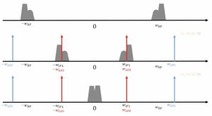
As shown in the figure, we can set the frequency of the second local oscillator exactly in the middle of our channel, and by doing this kind of mixing, the channel can be translated to the zero frequency. However, there is another problem: when the signal becomes its own image, as you see here, the negative frequency channel will become the image of the positive frequency channel.
So after down-conversion, these two channels will be translated to zero and corrupt the signal shape. Previously it was asymmetric, and now after down-conversion, it becomes takes a symmetrical shape. So basically, we are corrupting our data, and the solution for this problem is Quadrature down conversion.
Problem with dual IF receiver with zero IF2, when we want to convert asymmetrical channel to zero-IF down we will have an image problem, and the signal becomes its own image and as you see here is going to corrupt the channel, and there is a solution to this problem which is called quadrature down conversion.
Quadrature Signals
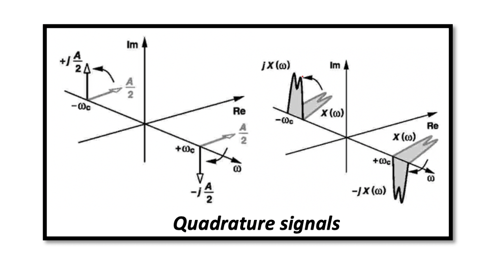
To understand quadrature down conversion, we need first to understand quadrature signals. We can call these two cosine and sine waves quadrature signals. The cosine wave can be written in exponential form and then find the Fourier transform. We get a combination of two deltas with two positive amplitudes. These are real values, and there are no imaginary parts in this equation.
For a sine wave, we can write it similarly, and the result we get is a positive and negative amplitude, and this equation has an imaginary part. So these are the quadrature signals here:

Representing quadrature signal in the time and frequency domain
In the time domain, these signals have a real part with a 90 deg phase difference. In the frequency domain, the cosine wave has two real parts and no imaginary part; however, the sine wave has imaginary parts with opposite signs.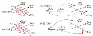
90 degree Phase shift
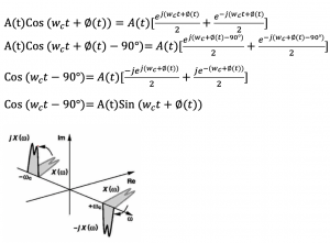
The cosine wave can be written in exponential form and find the Fourier transform, similar to the previous equation; however, we are using angular frequency here, so when we do the phase shift of this cosine wave, we get the sine wave.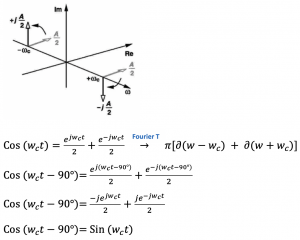
90-degree phase shift for narrowband modulated signal
The effect of a 90 deg phase shift on a narrowband modulated signal is shown below in the time domain. This is the time domain signal of the narrowband modulated data; let’s see what is happening when we do a 90-degree shift. So we can do a phase shift to narrowband modulated signal and reach the Sine wave. This can be shown in the frequency domain as well, so we have our channel, and we do exactly the same thing that is 90 degrees rotation clockwise and 90 degrees anticlockwise to reach the other signal and call these two quadrature signals. These quadrature signals are used in order to solve the image problem that we faced in the zero-IF receiver.
These quadrature signals are used in order to solve the image problem that we faced in the zero-IF receiver. In quarter down conversion, we create two versions of the down converter signal with a phase difference of 90 degrees.


