Secondary Image and Zero IF in Heterodyne Receiver
Secondary Image
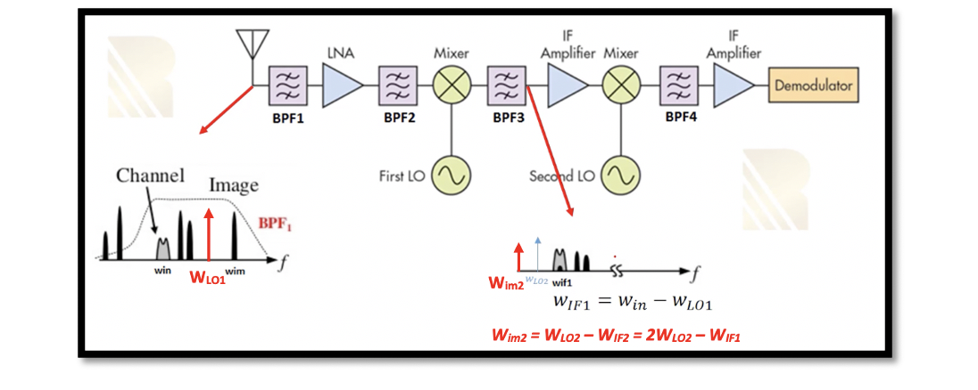
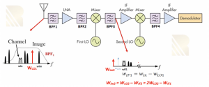
The major problem faced while designing a dual conversion heterodyne receiver is the secondary image problem. As shown in the figure, secondary image WIM2 is an IF frequency. BFP1 does not attenuate this signal as it is in IF frequency. This secondary image results from a combination of different frequencies due to the non-linearity of LNA, mixer, and local oscillator. The secondary image is not captured outside as it has an intermediate frequency and is far away from our band. The off-chip bandpass saw filter would attenuate and remove this signal. So this signal appears inside our receiver due to the non-linearity. When this signal goes through the second mixer, it gets translated inside our channel in IF2, blocking our signal. Therefore, the frequency of the second image is equal to the frequency of the second local oscillator minus WIF2 or 2WLO2 – WIF1.
How to remove secondary IF image?
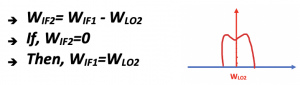
To remove the secondary image, we need to do a zero-second IF (WIF2=0).
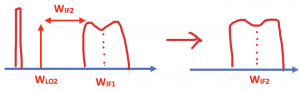
Imagine that we don’t have zero second IF, just like the previous section. We had WIF1 after the first down conversion as a center frequency of our channel, and we choose the WLO2 as shown in the below figure. So the difference between WIF1 and WLO2 is WIF2 which is a low frequency. WLO2 is the carrier, and WIF1 is our channel. At the end of the down-conversion, we get our channel WIF2. This case has an image problem, as previously discussed. So if there is an image signal at an equal distance from WLO2, it will be translated to the channel WIF2. To solve this problem, we do zero-second IF.
If we draw this equation, as shown above, we have our channel. The local oscillator frequency is equal to the center frequency of our channel. So, in this case, we won’t have any image problems.
If we want to translate to the down-conversion, because WIF2=0, in the end, we will be down-converting our channel to baseband. It means that our channel will be around the DC frequency; that is, the center frequency of our channel is zero. So in the transmitter, when we modulate our data, imagine the data is a random pulse, and the spectrum of the random pulse is like this kind of channel around the DC frequency.
In summary, we can say that in this kind of system, we translate our channel to zero frequency to avoid having the image. It can be shown as in the below figure where WLO2 is equal to the center frequency of our channel (WIF1), and at the end, our channel will be translated to zero-IF, which means the center frequency is equal to 0. Of course, if you have an interferer, it will also be translated to IF; however, we can get rid of the interferers using a high Q filter.
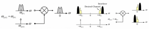
When signal becomes its own image (a problem in zero-IF)
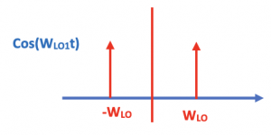
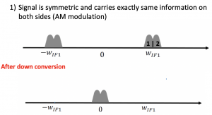
The signal can become its own image, as we know the signal is symmetric and carries exactly the same information on both sides (AM modulation). So, for example, if we find the Fourier transform for the carrier signal cos(WLOt), we see it has a positive component WLO and a negative component -WLO.
Similarly, it happens to our channel as well. When our channel is up-converted to higher frequencies, it has two identical information, positive and negative parts. Our channel is translated to WIF1, and we need to bring it to 0; we will now have two components -WIF1 and WIF1, as shown in the figure. Therefore, both channels will be translated to zero. If our signal is symmetric and it carries exactly the same information on both sides (1&2) after down-conversion and bringing it to 0, they match exactly. The signal may be amplified and have a high amplitude because we combined these two data, but it doesn’t lose its shape.
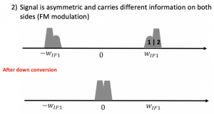
In the case of FM modulation, if a modulation doesn’t have the symmetrical shape or symmetrical channel as shown in sides 1 & 2 are asymmetrical. Our signal shape will totally change after down-conversion. The data will be corrupted, and this is the problem of the zero-IF.

Learn more about this topic by taking the complete course ‘RF System Design of Receivers, Transmitters & Transceivers – RAHRF409’.
Watch the course videos for more detailed understanding. Also checkout other courses on RF system and IC design on https://rahsoft.com/courses/.
Rahsoft also provides a certificate on Radio Frequency. All the courses offer step by step approach.
You may also like
Understanding Quadrature Amplitude Modulation (QAM) and Its Applications