What is Oscillator Pulling?
What is oscillator pulling and how is it generated?
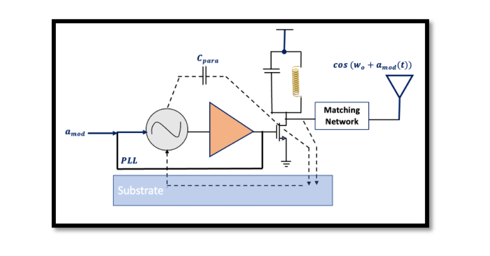
One of the problems faced while designing a transmitter is Oscillator Pulling or sometimes called Injection Pulling. The output power of a power amplifier is very high which we already know, hence there will be high swing as well (1W – 20Vpp), for 1W of power there will be 20 volts peak to peak voltage at the output. High voltage couples to various parts of the system through the silicon substrate, as shown in the diagram below, the voltage couples to the Local Oscillator (LO) through the substrate, so part of it will be injected into various blocks not only the LO. The parasite capacitance (Cpara) can become a problem in this circuit as it can be fit through the output port and can affect the local oscillator. The main focus on the oscillator here is because an oscillator is generally susceptible to any external periodic signal whose frequency is close to the oscillator frequency.


On the left side of the diagram imagine that there is gmsk modulation and this is a GMSK transmitter we have a signal which is a bit far away from the center frequency (wLO+∆w). This is our channel at the output of the power amplifier. So imagine the signal at the frequency of wLO+∆w is injected inside the local oscillator using the substrate. The external periodic signal injected into an autonomous oscillator can speed up or slow down the oscillation and this is called oscillator pulling.
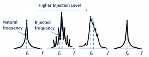
The above diagram shows noise from the output of PA injected to LO and the noise is a bit lower at the output of LO, we get our main component (carrier frequency) plus extra components. As we increase the amplitude of the injected signal, the main component starts moving to the right side, this is called the oscillator pulling. Finally, you can see the oscillator is not oscillating at the frequency of wo, because of this injected signal it will be pulled to the right side and it will get far from wo.
The diagram shows the output spectrum of the local oscillator, so this is the output of the local isolator and here we have a different kind of injection, it is exactly the reverse. so imagine that now this injected signal has a frequency of wo-∆w. We don’t need to always have a higher frequency compared to the center frequency, it can be lower as well, so in this picture, we can see its lower frequency. We are increasing the injection which means that we are increasing the amplitude of injecting signal as you see it starts pulling to the left side, and the output of the spectrum becomes symmetric, and then finally we will have a signal which is f0-∆f. Now the local oscillator is operating at a frequency that is not equal to the frequency of the carrier. This is one of the problems that we face, and we must solve this problem in the upcoming blogs where we are going to find the solution for oscillator pulling.


