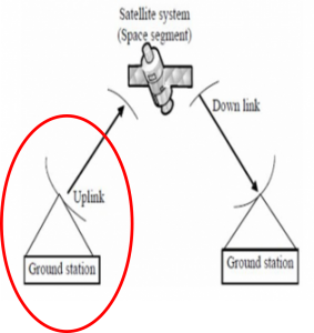
Link budget calculations for SATCOM – Uplink

For discussions regarding SATCOM downlink, read here: Link budget calculations for SATCOM – Downlink
This post explains the mathematical equation used to calculate the SNR of SATCOM uplink, or in other words, SNR of ground terminal signal as received at satellite antenna. The assumption is that reader is familiar with SATCOM link parameters including Receiver G/T (for uplink, RX is satellite and ground terminal is behaving as TX), Receiver Noise Temperature, Free Space Path Loss (FSPL), and Antenna Gain etc. And if you are not comfortable with these parameters, it is highly recommended to go through the details of SATCOM link parameters and their mathematical modelling, by reading these blogs:
- Free-Space Path Loss (FSPL) in Wireless Links
- Antenna Gain of ESA Terminal (Ground Station) in SATCOM
- Noise Temperature and G/T of Ground Terminal (Receiving System) in SATCOM
To start with, note that we are interested in Signal-to-Noise ratio at the input of the receiving system (satellite) and can be expressed as:
(SNR-per-Hz) Up = (C/No) Up = (Carrier Power in 1-Hz BW)dBm – (Noise Power in 1-Hz BW)dBm
Where,
- Carrier Power is the terminal signal power as received by the antenna of satellite receiver
- Noise power is the input-referred noise power seen by satellite receiver.
Carrier Power in 1-Hz BW
As mentioned earlier, Carrier Power is the terminal signal power as received by the antenna of satellite receiver. It can be expressed as follows:
Carrier Power in 1-Hz BW, dBm = (terminal TX EIRP) dBm – 10*log10 (terminal CH. BW) – (FSPL)dB – (Atmospheric Loss) dB + (Satellite Antenna Gain) dBi
where,
- (terminal TX EIRP) dBm = ground terminal Effective isotropic radiated Power in dBm.
- terminal CH. BW= ground terminal channel Bandwidth in Hz
- (FSPL)dB = Free-space path loss in dB. It can be expressed as follows.
FSPL, dB = 20*log10(d,km) + 20*log10(f,GHz) + 92.45
For details, read here: Free-Space Path Loss (FSPL) in Wireless Links - (Satellite Antenna Gain) dBi = Antenna Gain of Receiver/Satellite in dBi. It can be expressed as follows:
G(dBi)= Peak Gain (dBi) – Cosine roll-off * 10 * log10(cos theta)
For details, read here: Antenna Gain of ESA Terminal (Ground Station) in SATCOM. Although the discussions in the linked blog are in the context of Ground terminal, however, same concepts apply to Satellite Antenna too.
Noise Power in 1-Hz BW
As mentioned earlier, Noise power is the input-referred noise power seen by satellite receiver. It can be expressed as follows:
Noise Power in 1 Hz BW, dBm = 10*log10(k.T) + 30
- k= Boltzman’s constant = 1.381 x 10⁻²³ J/K
- T= Input-referred Noise temperature (in Kelvins) of the satellite receiver. To know further about Noise temperature of a receiving system, read here: Noise Temperature and G/T of Ground Terminal (Receiving System) in SATCOM. Although the discussions in the linked blog are in the context of Ground terminal, however, same concepts apply to satellite too when it is behaving as a Receiver for uplink.
- 30 is being added to 10*log10(k.T) for converting it from dBW to dBm.
Calculating the SNR-per-Hz of Uplink
(C/No) Up =(terminal TX EIRP) dBm – 10*log10 (terminal CH. BW) – (FSPL)dB – (Atmospheric Loss) dB + (Satellite Antenna Gain) dBi – 10*log10(k.T) – 30
We can rewrite above equation as:
(C/No) Up =(terminal TX EIRP) dBm – 10*log10 (terminal CH. BW) – (FSPL)dB – (Atmospheric Loss) dB + (Satellite Antenna Gain) dBi – [10*log10(k) + 10*log10(T) + 30 ]
Subtracting the terminal channel bandwidth from the full terminal EIRP gives the terminal transmit power in 1-Hz bandwidth. Subtracting the FSPL and atmospheric attenuation, and then adding the Satellite Receive Antenna Gain provides the power at the input of satellite receiving system (also in a 1 Hz BW).
[10*log10(k) + 10*log10(T) + 30] provides the input noise power (in dBm) for the satellite receiver, where T is the noise temperature of the receiving system including antenna , RF chain and LNB – it accounts for the antenna noise as well as the input-referred noise contribution by the rest of the receiver . Finally, subtracting input noise floor (per Hz) of the receiver from the input carrier power (per Hz) produces the overall input signal-to-noise ratio in a 1 Hz BW.
Next, we can lump satellite Gain and noise-temperature parameters into a single entity called as satellite Receiver G/T. Finally, the uplink SNR equation takes the form as follows:
(C/No) Up = (terminal TX EIRP) dBm – 10*log10 (terminal CH. BW) – (FSPL)dB – (Atmospheric Loss) dB + (Satellite G/T) dB/K – 10*log10(k) – 30
- Where, (Satellite G/T) dB/K = (Terminal Antenna Gain) dBi – 10*log10(T)
- (terminal TX EIRP) dBm = terminal operating power (dBm) + terminal antenna Gain (dBi)
- terminal operating power (dBm) = It is usually the maximum power for terminal TX linear operation (output P1dB of the terminal transmitter).
It can be observed that increasing terminal TX EIRP (terminal TX output P1dB and terminal Gain) improves the Uplink SNR.

Learn more about this topic by taking the complete course ‘RF System Design of Receivers, Transmitters & Transceivers – RAHRF409’. Watch the course videos for more detailed understanding. Also checkout other courses on RF system and IC design on https://rahsoft.com/courses/. Rahsoft also provides a certificate on Radio Frequency. All the courses offer step by step approach.
Tag:Link Budget, SATCOM, Uplink


