Understanding Transducer Power Gain
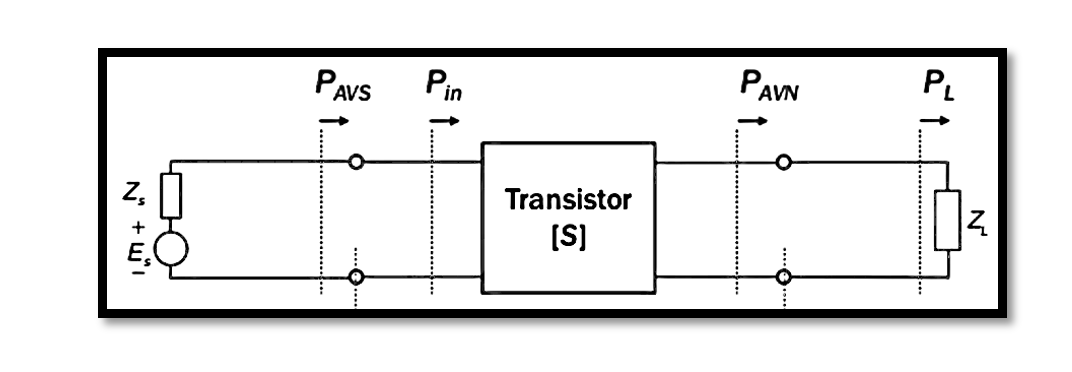
Transducer power gain, denoted as GT, encapsulates the ratio between PL and PAVS, representing the power delivered to the load and the power available at the source, respectively. In simpler terms, it measures how effectively power is transferred from the source to the load through the transducer.
Examining a typical two-port network diagram elucidates this concept further. Initially, we have a certain amount of available power, a fraction of which is transmitted through the network due to potential matching issues. Subsequently, this transmitted power undergoes amplification before being delivered to the load. This scenario highlights the interplay between available power, power transmission, and amplification within the network.
The transducer power gain directly correlates with the impedance matching at both input (Zs) and output (ZL) terminals. Achieving impedance matching ensures optimal power transfer efficiency. When there’s impedance mismatch between the source (Zs) and input (Zin), the power delivery dynamics alter, consequently affecting the gain. Therefore, maintaining matching conditions—where Zs equals Zin conjugate and ZL equals Zout conjugate—is paramount. This alignment guarantees maximum power transfer from the source to the network, amplification of this power within the network, and eventual delivery of the amplified power to the load without loss or impedance discrepancies.

Maximizing Transducer Power Gain: Impedance Matching
In transducer power gain, a pivotal condition arises when both input and output are conjugately matched to the two-port device. This configuration results in maximum gain, a fundamental principle rooted in the avoidance of power loss.
Impedance matching at both input and output terminals ensures efficient power transfer without loss. If there’s a lack of matching, power loss occurs, undermining the effectiveness of the system. Conversely, achieving matching optimizes power flow from input to output.
In this scenario, the transducer power gain (GT) equals the available power gain (GA), representing a special case of gain maximization. The rationale behind this equivalence is straightforward. Consider GT, which denotes the ratio of power delivered to the load (PL) to the input power (Pin). With matching, the available power at the source (PAVS) equals the input power (Pin). Consequently, GT simplifies to PL/PAVS, which inherently defines the transducer power gain.
In essence, impedance matching ensures that the power available at the source aligns with the input power, maximizing power transfer efficiency and amplification within the network. This fundamental principle underscores the significance of impedance matching in transducer systems, where maximizing gain is paramount for optimal performance.
Equivalence of Transducer Power Gain: Matching Conditions
In understanding transducer power gain, it’s crucial to acknowledge the roles of input and output matching in maximizing gain efficiency. The transducer power gain (GT) delineates the power ratio between the source and the power available at the output of the network (PAVN). With output matching, PAVN represents the maximum power deliverable to the load (PL), thus aligning PAVN with PL.
Consequently, the available gain (GA) stems from the source and is defined as PAVN over PAVS. When output matching is achieved, PAVN equates to PL, rendering GA equivalent to GT. This correspondence underscores the importance of matching conditions in facilitating optimal power transfer from source to load.
Summary of Power Gain Concepts
In conclusion, let’s recap the key concepts surrounding power gain and impedance matching in transducer systems, setting the stage for further exploration of equations and examples.
1. Power Gain (G):
Power gain (G) represents the ratio of output power to input power. It remains a function of the load impedance (ZL) but is independent of the source impedance (ZS). This independence stems from the observation that altering ZS affects both input and output powers proportionally, thus maintaining a constant ratio.
2. Available Power Gain (GA):
Available power gain (GA) quantifies the power transfer efficiency from input to output within the system. It depends on the source impedance (ZS) but remains unaffected by changes in the load impedance (ZL). This invariance is demonstrated by the consistent maximum power delivery to the load despite variations in ZL.
3. Transducer Power Gain (GT):
Transducer power gain (GT) encompasses the entire power transfer process from input to output, considering both source and load impedances (ZS and ZL, respectively). Achieving impedance matching—where Zin equals ZS conjugate and Zout equals ZL conjugate—ensures maximum power transfer efficiency. In matching conditions, GT, GA, and G coincide, reflecting optimal power gain performance.
In summary, understanding these principles elucidates the significance of impedance matching in maximizing power transfer efficiency within transducer systems. Exploring equations and examples will further solidify these concepts and their practical applications.

Learn more about this topic by taking the complete course ‘Microwave Amplifier and Low Noise Amplifier (LNA) Design Theory and Principles online course – RAHRF526’. Watch the course videos for more detailed understanding. Also checkout other courses on RF system and IC design on https://rahsoft.com/courses/. Rahsoft also provides a certificate on Radio Frequency. All the courses offer step by step approach.


