Stability of Simple Charge Pump Phase-Locked Loops (CPPLL)
Introduction
Charge Pump Phase-Locked Loops (CPPLLs) are widely used in electronic systems to synchronize the frequency of oscillators. A crucial aspect of designing CPPLLs is ensuring their stability. This blog explores the stability of a simple CPPLL, discussing key concepts, equations, and methods to improve stability.
Closed Loop Transfer Function
The closed-loop transfer function is essential for analyzing the stability of CPPLLs. For a simple CPPLL, the transfer function is given by:

Analyzing this transfer function reveals that there are two poles on the jωj\omegajω axis, indicating potential instability in the system.

Open Loop Transfer Function and Instability
The open-loop transfer function helps further understand the stability issues. It is represented as:

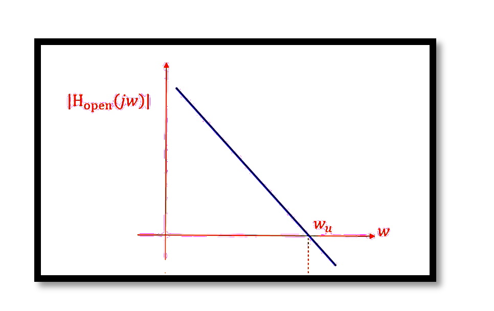
The Bode plot of the open-loop transfer function shows a -180-degree phase shift, signifying instability. This phase shift occurs because the system lacks sufficient phase margin.
Solution: Adding Resistor R1
To improve stability, we introduce a resistor R1 in series with the capacitor C1 in the loop filter. The impedance Z1 becomes:


Damping Factor and Natural Frequency
The stability of the modified CPPLL can be analyzed using the damping factor (ζ) and the natural frequency (ωn):

Increasing Icp, R1, and KVCO enhances stability. However, it’s essential to choose the right component to adjust for the desired stability without affecting other performance metrics.
Take our entry level course (Below) for free using coupon code RAHRF101BLOG
RF Fundamentals, Basic Concepts and Components – RAHRF101
For limited time take an additional 10% off of all our courses using coupon code RFCERT10
Rahsoft RF Certificate and courses
Graphical Representation
The Bode plot of the modified open-loop transfer function demonstrates improved stability. The phase margin is significantly increased, resulting in a more stable system. The introduction of R1 creates a zero that counteracts the negative phase shift, reducing the slope from -40 dB/dec to -20 dB/dec at the frequency wz.

The inclusion of the resistor R1 in the CPPLL circuit not only alters the open-loop transfer function but also introduces a zero in the transfer function, significantly enhancing system stability. The revised open-loop transfer function now is:

This introduction of a zero at ωz=1/R1C1 shifts the system dynamics. Graphically, this is represented in the Bode plot where the slope of the magnitude plot changes from -40 dB/decade to -20 dB/decade at the frequency ωz. This change effectively reduces the rate at which the gain decreases, thus improving phase margin and system stability. In the phase plot, the phase starts to increase around the zero frequency ωz, improving the overall phase margin significantly. The phase margin (PM) is enhanced to around 80 degrees, a substantial improvement from the initial unstable condition where the phase margin was near zero. The phase margin is given by:

where ωu is the unity gain bandwidth. With the zero’s introduction, the phase at ωu is increased, leading to a higher phase margin. Additionally, the argument of the open-loop transfer function Hopen(s) now includes a term:

This term reflects the phase lead introduced by the zero, further contributing to the improved stability. The system’s gain crossover frequency is modified, ensuring that the system remains stable under a wider range of operating conditions.
This graphical representation of the open-loop transfer function highlights the improved stability with the introduction of the resistor R1. The zero introduced by R1 counteracts the negative phase shift, providing a positive phase contribution, thus ensuring that the CPPLL operates stably with a significant phase margin.
Conclusion
Ensuring the stability of CPPLLs is vital for their reliable operation. By adding a resistor in the loop filter, the phase margin is improved, leading to a stable system. The key parameters Icp, R1, and KVCO play crucial roles in determining the overall stability. Proper tuning of these parameters can enhance the performance and stability of CPPLLs in practical applications.

Learn more about this topic by taking the complete course ‘Phase Lock Loop System Design Theory and Principles RAHRF469’. Watch the course videos for more detailed understanding. Also checkout other courses on RF system and IC design on https://rahsoft.com/courses/. Rahsoft also provides a certificate on Radio Frequency. All the courses offer step by step approach.


