Power Amplifier Class Comparisons: Detailed Calculation Examples for A, B, and C
Amplifiers are a crucial component in many electronic systems, with their primary function being to increase the power of a signal. Among the different amplifier classifications, Classes A, B, and C are widely used, each offering unique advantages and challenges. In this blog, we will explore the key characteristics of these amplifier classes, their operational principles, and efficiency calculations.
Overview of Amplifier Classes
Amplifiers are categorized into different classes based on the conduction angle, which is the portion of the input signal during which the transistor conducts. The conduction angle (α) is a critical parameter that determines the linearity, efficiency, and power output of the amplifier. Below is a brief overview of each class:
Class A Amplifiers:
- Conduction Angle: α=360∘ or 2π radians.
- The transistor conducts during the entire input signal cycle.
- Offers high linearity and fidelity.
- Efficiency is relatively low because the transistor is always on.
Class B Amplifiers:
- Conduction Angle: α=180∘ or π radians.
- The transistor conducts for half of the input signal cycle.
- Improved efficiency over Class A.
- Crossover distortion is a common issue due to the transition between transistors.
Class C Amplifiers:
- Conduction Angle: α<180∘
- The transistor conducts for less than half of the input signal cycle.
- High efficiency, but poor linearity.
- Typically used in RF applications where efficiency is prioritized over linearity.
Current and Efficiency Calculations
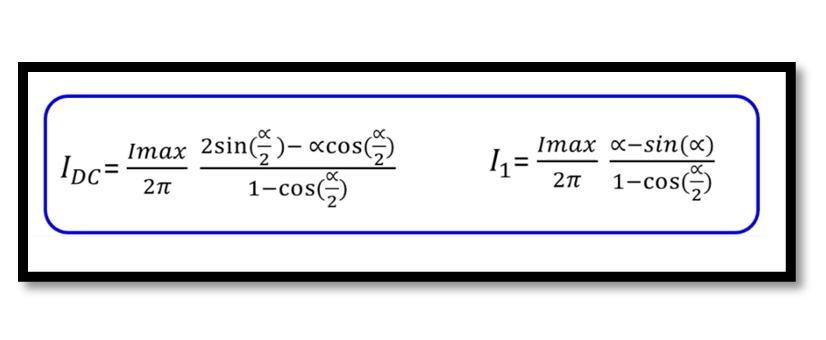
To better understand the operational differences, let’s delve into the current calculations and efficiency for each class. We will start with the DC current IDC and output current I1 for Classes A, B, and C, and then calculate the efficiency for Class B as an example.
Class B Amplifier: For a Class B amplifier, the DC current IDC and output current I1 are given by:

To calculate the efficiency μ of a Class B amplifier:

Here, the output power Pout and DC power Pdc can be expressed as:

Substituting the values of IDC and I1:

This high efficiency is one of the key advantages of Class B amplifiers, although it comes at the cost of possible distortion.
Class C Amplifier: For Class C amplifiers, the output current I1 can be found using the following equation, assuming α= π/2

This equation shows that the current in a Class C amplifier is significantly reduced compared to Class B, reflecting the increased efficiency but reduced conduction time.
Comparative Analysis
Efficiency:
- Class A amplifiers offer the lowest efficiency, typically around 25-30%, because the transistor conducts for the entire cycle.
- Class B amplifiers offer a significant improvement with an efficiency of about 78.5%, as calculated.
- Class C amplifiers can achieve even higher efficiencies, often exceeding 80%, but with the trade-off of increased distortion and limited linearity.
Linearity:
- Class A amplifiers provide the best linearity, making them ideal for high-fidelity audio applications.
- Class B amplifiers have moderate linearity with some crossover distortion.
- Class C amplifiers have the poorest linearity and are generally unsuitable for audio applications.
Take our entry level course (Below) for free using coupon code RAHRF101BLOG
RF Fundamentals, Basic Concepts and Components – RAHRF101
For limited time take an additional 10% off of all our courses using coupon code RFCERT10
Rahsoft RF Certificate and courses
Conclusion
Each amplifier class has its specific use cases based on the trade-offs between efficiency, linearity, and complexity. Class A is chosen for its superior fidelity in low-power applications, Class B is commonly used in audio power amplifiers due to its balance between efficiency and distortion, and Class C is preferred in RF applications where efficiency is paramount. By understanding the underlying principles and calculations, engineers can make informed decisions about which amplifier class to use in their designs, optimizing for the desired performance characteristics.

Learn more about this topic by taking the complete course ‘Linear RF Power Amplifier (PA) Design Theory and Principles online course – RAHRF562’. Watch the course videos for more detailed understanding. Also checkout other courses on RF system and IC design on https://rahsoft.com/courses/. Rahsoft also provides a certificate on Radio Frequency. All the courses offer step by step approach.
Tag:Class A, PA, POwer Amplifier


