Understanding QPSK Signal Constellation and Demodulation
Introduction
Quadrature Phase Shift Keying (QPSK) is one of the most commonly used digital modulation schemes due to its efficiency in bandwidth utilization and robustness against noise. It encodes two bits per symbol by shifting the phase of the carrier wave to one of four possible states. This blog provides a deep technical insight into QPSK signal constellation and demodulation, discussing its mathematical formulation, constellation diagram, signal space representation, and demodulation process.
QPSK Signal Constellation
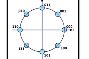
The QPSK signal constellation is a representation of the transmitted symbols in a two-dimensional plane where each symbol corresponds to a unique phase shift. It utilizes four distinct phase shifts, each separated by 90 degrees, representing two-bit pairs.
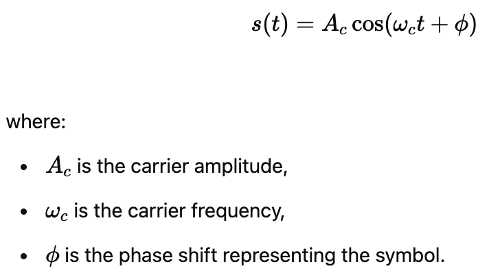
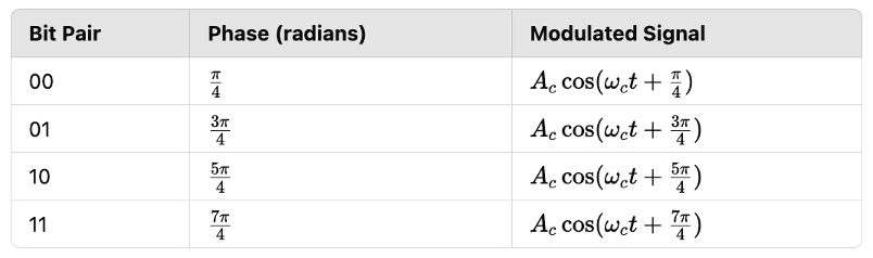
Mathematical Representation The transmitted QPSK signal can be expressed as:
The four possible phase shifts in QPSK correspond to the following symbol mappings:
Constellation Diagram The QPSK constellation consists of four points, each located at equal distances from the origin in the complex plane. The signal points can be represented as:
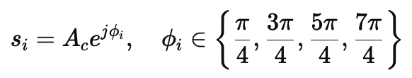
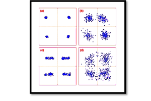
where Si are the complex symbols representing different phase shifts. The constellation diagram clearly shows that each symbol is equidistant, minimizing the probability of detection errors in the presence of noise.
QPSK Demodulation
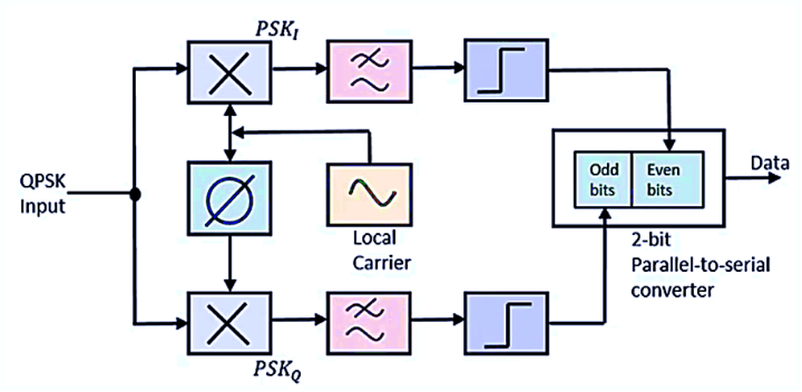
The demodulation of QPSK signals involves extracting the in-phase (I) and quadrature (Q) components from the received signal and mapping them back to their respective bit pairs.
Step-by-Step Demodulation Process
- Received Signal Representation: The received signal at the receiver is given by:
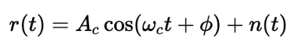
where n(t) represents the additive noise in the communication channel.
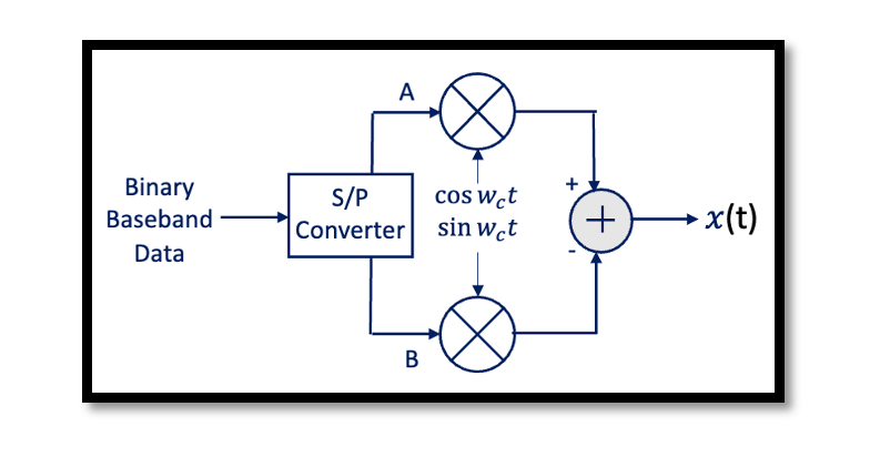
2. Quadrature Detection: The signal is passed through two coherent detectors:
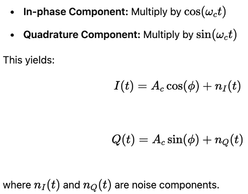
3. Low-Pass Filtering: The multiplied signals are passed through low-pass filters to remove high-frequency components, isolating the baseband signals and .
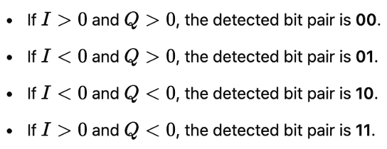
4. Decision Device: The filtered I and Q components are compared against a predefined threshold to determine the received symbol.
5. Parallel-to-Serial Conversion: The detected bit pairs are reassembled into a serial data stream, reconstructing the original transmitted information.
Error Performance of QPSK
The Bit Error Rate (BER) of QPSK in an additive white Gaussian noise (AWGN) channel is given by:
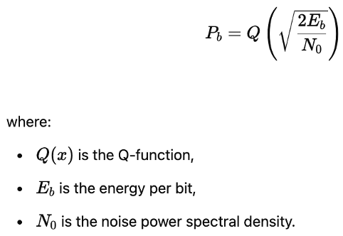
QPSK achieves the same BER as Binary Phase Shift Keying (BPSK) but transmits twice the data rate for the same bandwidth, making it more spectrally efficient.
Take our entry level course (Below) for free using coupon code RAHRF101BLOG
RF Fundamentals, Basic Concepts and Components – RAHRF101
For limited time take an additional 10% off of all our courses using coupon code RFCERT10
Rahsoft RF Certificate and courses
Conclusion
Quadrature Phase Shift Keying (QPSK) is a widely used digital modulation technique due to its ability to transmit two bits per symbol efficiently. The QPSK signal constellation consists of four distinct phase shifts, allowing robust communication even in the presence of noise. The demodulation process involves coherent detection, quadrature decomposition, filtering, and threshold-based decision-making to recover the transmitted bits. With applications in wireless communications, satellite systems, and broadband transmission, QPSK remains a critical modulation scheme in modern digital communications. Understanding its signal space representation and demodulation process is crucial for designing efficient communication receivers that maximize data transmission reliability.

Learn more about this topic by taking the complete course ‘Introduction to Modulation in Communication Systems Online Course – RAHRF152’. Watch the course videos for more detailed understanding. Also checkout other courses on RF system and IC design on https://rahsoft.com/courses/. Rahsoft also provides a certificate on Radio Frequency. All the courses offer step by step approach.
You may also like
Understanding Quadrature Amplitude Modulation (QAM) and Its Applications