Power Gain and Voltage Gain in dB
We know that the unit of power is watts; however, in RF systems, we measure power in decibels. A decibel is a logarithmic unit that indicates ratio or gain. When converting the power to decibels, it is compared to a reference level. This reference level is 1 watt for the dB domain. PdB is a ratio, and power is shown in the logarithmic domain.
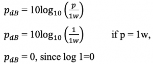
It is comparing power with 1-watt power in decibels. If P=1, then PdB =0; however, it doesn’t mean that the power is 0. It means the power is 1W.
Most of the RF circuits are analyzed in the power domain, specifically in microwave the power quantity is preferred over other quantities. Power gain is an important feature in analyzing these systems. Power gain is similar to voltage gain; it is the ratio of output power to input power and can also be represented in the log domain.

For example, if input power is 0 dB and output power is 10 dB, the dB domain’s power gain is 10 dB.
Voltage gain is the ratio of output voltage to input voltage, measured in log domain as shown: In voltage gain a factor of 20 is multiplied to log, this is because Pout=Vout2/R, the 2 in log domain gets multiplied to 10 to get 20.

Take our entry level course (Below) for free using coupon code RAHRF101BLOG
RF Fundamentals, Basic Concepts and Components – RAHRF101
For limited time take an additional 10% off of all our courses using coupon code RFCERT10
Rahsoft RF Certificate and courses
Power in dBm
In dBm the reference level is 1mW (one milliwatt) and power gain in dBm is measured similarly to dB. The relation between dB and dBm is, there is a 30dBm difference.


As discussed in matched networks, while designing matching circuits for RF blocks, the power quantities are considered. For example, if we take a Low Noise Amplifier (LNA), the input impedance to the LNA is 50ohms, and if the desired output impedance is also 50ohms, the input and output power for this kind of matched block will be calculated as:
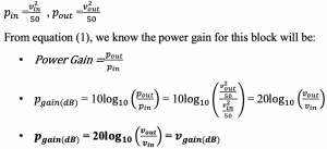
This shows that the power gain is equal to the voltage gain; hence, the RF circuits are analyzed in power quantities. However, this is true only in the case where the power is matched.
Power in off-chip circuit

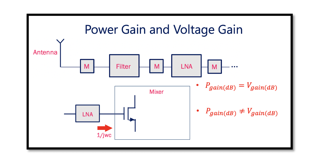
In an off-chip circuit, the components are placed discretely and are not in an integrated form. All the modules are designed to have matched networks. Read about matching network. If the input impedance to the block is 50 ohms, then we get the output impedance of 50 ohms. Hence, we can say that in this kind of circuit, the power gain will be equal to the voltage gain.
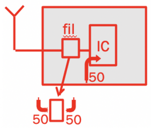 There can also be a circuit where we have one module as off-chip, and all other modules are inside Integrated circuit (IC). For example, as shown here, the filter is off-chip and other modules are integrated. Here the input impedance is to the filter is 50 ohms, and the input to the IC is tuned to 50 ohms and there is a matching network between the filter and IC. However, there is no matching networks inside an IC.
Power in Intregated Circuits (IC)

In an Integrated circuit (IC), all the modules are integrated into one chip. There are only 50 ohms input impedance. But there is no matching network between the blocks inside an IC. Here, the power gain is not equal to the voltage gain.
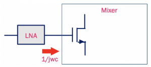
As shown in the diagram, inside an IC, the LNA is connected directly to the mixer without a matching network between. In a mixer circuit, we have a transistor with purely imaginary part for the input impedance. The power delivered to this mixer will be 0, as the average power for capacitance = 1/jcw=0. Therefore, an in an IC design the voltage quantity is preferred over the power quantities, and there is no matching networks inside IC. Hence, the input and output of cascade stages are not equal and contains some real parts.
In summary, for the off-chip circuit, we work with power quantities and have matched networks, and in the case of IC design, there is no power matching, and voltage quantities are analyzed.

Learn more about this topic by taking the complete course ‘’RF Design Theory and Principles – RAHRF201’’.
Watch the course videos for more detailed understanding. Also checkout other courses on RF system and IC design on https://rahsoft.com/courses/
Rahsoft also provides a certificate on Radio Frequency. All the courses offer step by step approach.
Tag:IC, Off-chip circuit, Power gain, Voltage gain


