Transfer Function, Bandwidth and Quality Factor in RLC circuits
Defining the Transfer function for series RLC circuits
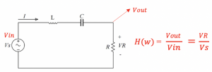
Transfer function {H(w)} is equal to output voltage Vout divided by input voltage Vin which can be further written as:
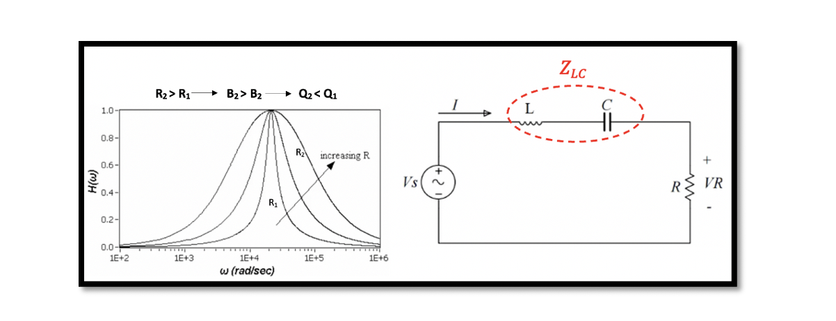
The graph represents the magnitude versus frequency. There are three different transfer functions shown in the diagram. Changing the resistance within the circuit changes the width of the transfer function; increasing the resistance increases the width acting like a bandpass filter. The bandpass filter allows passing only a specific frequency band, rejecting any frequencies outside the band limit.
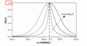
The diagram shows that it is a very narrow bandpass filter, which passes frequency components only in resonance frequency. So assuming fo is the resonance frequency with the magnitude of transfer function 1.0, we can say at this point VR=Vs, it means that we can transfer all power within this frequency to the output of our circuit. For example, if you have power or signal within this narrow band, it will be moved to the output; however, if you have a signal outside of this band, it will be attenuated by the circuit. So this circuit acts as a bandpass filter.
Take our entry level course (Below) for free using coupon code RAHRF101BLOG
RF Fundamentals, Basic Concepts and Components – RAHRF101
For limited time take an additional 10% off of all our courses using coupon code RFCERT10
Rahsoft RF Certificate and courses
How can we have a transfer function of 1.0 for the circuit at the resonance frequency?
At the resonance frequency, these impedances (L & C), the equivalent impedance ZLC, will become zero. Basically, at the resonance frequency, the equivalent circuit of this network will only have resistance, as shown in Figure 2. Hence, VR becomes equal to Vs.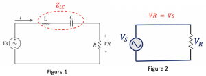
Bandwidth
At a certain frequency, the power dissipated by the resistor is half of the maximum power then the amplitude of the voltage across the resistor becomes equal to 1/√2 of the maximum voltage.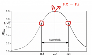
This diagram represents the transfer function, and we defined two points w1 and w2. The amplitude of this point is 1/√2 of the maximum voltage. The maximum transfer function is at point A where VR=Vs, the maximum power that can be achieved at the output. The power will be less at any other point within the graph shown as the gain is less than 1. The difference between the two frequencies w1 and w2, is called bandwidth.
Now we can see the relationship between resistor, inductor, and bandwidth. Hence, this is the reason why in figure 3, for series RLC the resistance increases with an increase in bandwidth.
Quality Factor
The quality factor is defined as the ratio of resonance frequency (fr)to bandwidth; however, this definition is true only when there is resonance (L & C) in the circuit.
The common definition for quality factor is the ratio of the energy stored in the oscillating resonator to the energy dissipated per cycle.
Here, power loss is related to the resistor, and we don’t have power loss in the inductor or capacitor (as discussed in the section active and reactive power). The inductor and capacitor are dissipating or generating the reactive power, but when we say power loss, that is the active power related to the resistor in the circuit. If we have more power loss, then we will have a low quality factor (Q). Low Q networks are not efficient due to more power loss. So the aim is to have high Q in the circuits.
How to find Quality Factors in RLC circuits?
As we know, that quality factor is the ratio of resonance frequency to bandwidth; therefore we can write the equation for the RLC circuit as:
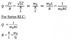
- When the transfer function gets narrow, the quality factor is high.
- The quality factor increases with decreasing R.
- The bandwidth decreased with decreasing R.
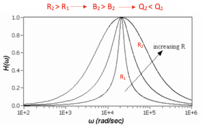
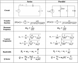
Table for RLC series and parallel equations:
