Understanding the Structure of Sliding IF Receivers
What is Sliding IF receivers?
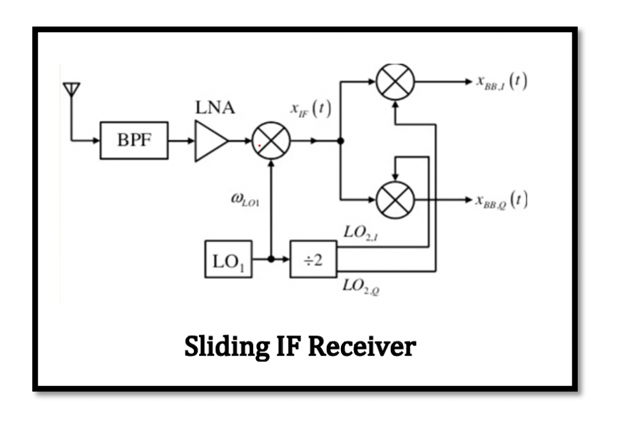
In the previous section zero-IF heterodyne receiver, the receiver structure is shown having three mixers that means three local oscillators. The first mixer is for the radio frequency and next two mixers are used for the quadrature down conversion. In reality we cannot use local oscillators in one receiver structure, as oscillators fabricated on one chip suffers from unwanted coupling creating more problems. Therefore, only one oscillator is employed that is used to produce the required frequencies. This type of receiver is called sliding IF receiver. As shown in the below figure of sliding IF receiver. We have two down conversion steps for this receiver. First IF is called xIF from the RF mixer, second part is zero IF, which mean we are down converting the signal around the zero frequency and is also quadrature down conversion in order to remove the secondary image. Read more about secondary image and zero IF heterodyne receiver.
So sliding IF receiver structure uses only on local oscillator and other frequencies are derived from it and this local oscillator LO1 is called the source oscillator. LO1 is connected to the first mixer. For the second mixers for the quadrature down conversion the frequency is divided, that is the frequency of second mixer is half of the frequency of local oscillator. The sliding IF receivers LO1 can be divided by 2, as well as 4 or 8.
The frequency divider block divides the local oscillator frequencies for the other mixers to do the quadrature down conversion. The frequency divider has two tasks to perform in this structure, firstly to divide the frequency for the mixers and secondly to do the 90-degree phase shift of the frequency producing two outputs cosine and sine waves that is required for the quadrature down conversion for restoring our data.
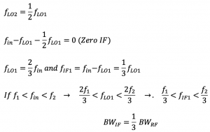
If we have a band between f1 and f2 filtered using the bandpass filter, what will be the range of local oscillator and first IF? Here fin is the input frequency. Using the above equation fLO1 and fIF1 can be calculated, and it can be noticed that the bandwidth of fIF1 is lower than bandwidth of RF. Therefore, first IF filter must exhibit narrow bandwidth.
Normalized Bandwidth
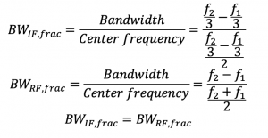
The normalized bandwidth is defined as the bandwidth over the center frequency of the bandwidth. As it can be seen from the equations that the normalized bandwidth of both IF and RF are equal unlike the normal bandwidth.
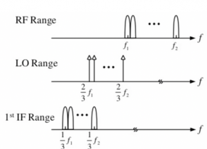
The below figure shows what is happening inside of our receiver. The bandpass filter picks the band between f1 and f2. The frequency of local oscillator within our receiver is not constant, as we are tuning it. If f1 is the channel picked for down conversion, then the local oscillator frequency tined for this will be 2/3 f1. The RF mixer which is the first mixer helps with this mixing and then in output we get the first IF. After the first mixer comes the quadrature down conversion for zero IF. Similarly the other channels also get converted. When the frequency of LO1 is tuned the frequency of other two mixers also changes automatically.
The purpose of using the quadrature down conversion is to avoid having the secondary image, that is to have zero IF however, the first IF has the image problem. Read about the image signal in receiver. The image band has the same range as IF range. To get rid of this image we have filters. First filter is bandpass filter but it cannot attenuate the image signal, hence there is a mild bandpass filter designed as part of the LNA. Usually, a mild on-chip bandpass filter to suppress the image signal. There won’t be a secondary image signal as then comes the quadrature down conversion to restore our data before demodulation through digital data processing. This is the purpose of using this kind of structure so that we can restore our data and solve the problem where the signal becomes its own image.
When the sliding IF recevier LO is divided by 4
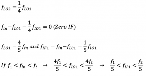
When the LO1 is divided by 4, the second frequency is quarter of the first local oscillator. The bandwidth of IF is even smaller than the first part when LO1 was divided by 2, so we said first IF filter mist exhibit narrow bandwidth. In the first part it was like 1/3 of the bandwidth of the input band but now its 1/5th so it’s getting smaller and smaller.

Learn more about this topic by taking the complete course ‘RF System Design of Receivers, Transmitters & Transceivers – RAHRF409’.
Watch the course videos for more detailed understanding. Also checkout other courses on RF system and IC design on https://rahsoft.com/courses/.
Rahsoft also provides a certificate on Radio Frequency. All the courses offer step by step approach.


