Introduction to Direct Conversion Receivers
How is the Structure of Heterodyne Receiver?
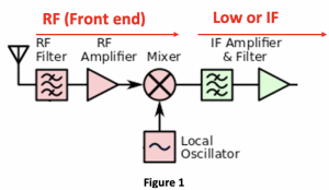
Till now we have discussed on various structures for heterodyne receivers and the image problem faced by the receiver. The first simple structure discussed is shown in figure 1. Read about the heterodyne receiver and its components. In the basic structure there is an off-chip RF filter for selecting the band and it is connected to the Low Noise Amplifier and mixer. The band is amplified and then down converted by the mixer for which local oscillator is required. These blocks forms the RF front end of the receiver. At the output of the mixer we get the intermediate frequency. This basic structure faces the problem of trade-off between selecting the channel and rejecting image. If the local oscillator frequency is selected close to the band, there would be a problem with rejecting the image signal however we will be able to translate and convert the channel to low IF. Therefore, channel selecting will be easier. If the local oscillator frequency is selected far from the band there won’t be a problem with image rejection, but we will have high IF however, a high Q filter cannot be designed for selecting the channel. That’s where the second structure comes in where two local oscillators are used.
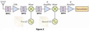
First LO is far from the band to have better image rejection and the second LO is close to the band so that the channel can be selected with designing filters. This type of structure is called the dual conversion receiver. Read about dual conversion heterodyne receiver. The first part of this structure is for image rejection hence high IF and the second part is for channel selection hence low IF. So now due to two IF frequencies we have secondary image problem in the structure, therefore we try to make the frequency of second IF equal to the frequency of first IF to have zero IF. Read about secondary image and zero IF heterodyne receiver. To remove the secondary image, we need to do a zero-second IF (WIF2=0). The channel will be down converted around the zero frequency. In modern receivers all the off-chip filters are part of the block circuit design except the first bandpass filter which is off-chip. The LNAs are tuned to work in desired frequency band, there is input and output matching circuits in the LNA block which kind of acts like a bandpass filter.
The problem now faced by the dual conversion receivers are in zero IF the signal becomes its own image. As the signal is symmetric it has positive and negative parts. When our channel is up-converted to higher frequencies, it has two identical information, positive and negative parts. Therefore, both channels will be translated to zero. Our signal shape will totally change after down-conversion. The data will be corrupted, and this is the problem of the zero-IF. Hence, the third structure is introduced where the second part of the structure is replaced for quadrature down conversion.
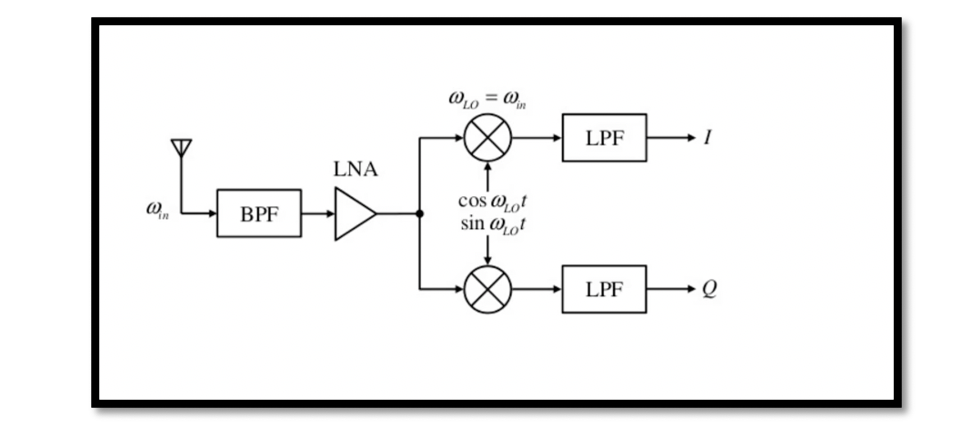
Figure 3 shows the structure of zero IF receiver, where the first part remains the same as dual conversion receiver, however, the zero IF part is replaced with two mixers for producing the quadrature signals in order to solve the image problem that we faced in the zero-IF receiver. Read about zero IF receiver and quadrature down conversion. In quarter down conversion, two versions of the down converter signal with a phase difference of 90 degrees is created. This quadrature down conversion uses two mixers, one fed with a cosine wave and the other with sine wave. So the same IF data will go to two different paths in order to be changed to quadrature signals. Later on in the digital signal processing the data can be retrieved without corrupting it. So this structure uses three local oscillators, however using three oscillators in one receiver can have problems where they starts coupling. Oscillators fabricated on one chip suffers from unwanted coupling creating more problems.

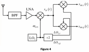
Therefore, the fourth structure is introduced as shown in figure 4 having only one oscillator which is employed to produce the required frequencies. The local oscillator LO1 called the source oscillator is connected to the first mixer. For the second mixers to do the quadrature down conversion the frequency is divided, that is the frequency of second mixer is half of the frequency of first local oscillator. The frequency divider block divides the local oscillator frequencies for the other mixers to do the quadrature down conversion. Depending on the application structure the frequency divider can be 2, 4 or 8. Read about the structure of sliding RF receivers.
What are direct conversion receivers (homodyne receivers) ?
As a summary we can say that we are trying to down convert RF to IF. At first it was to down convert from RF to IF1 and then to IF2 which is changed to zero IF for the image problem.
If we down convert RF directly to zero IF with one mixer, we are doing the direct down conversion and hence, this type of structure is called the Direct Conversion Receivers. The direct conversion receivers are also called the homodyne receivers. The down conversion has only one step in this receiver type, from RF to zero IF.
Advantages of homodyne receivers:
- It has a simple design and there is no image problem.
- The channel selection is done by low pass filters. Low pass filters are on-chip and are active filters.
- It is simple to handle as the mixing spurs are significantly reduced in number.


