How Phase-Noise affects RF System Performance?
Are you wondering about calculating Phase-Noise requirements for a certain wireless communication link? If yes, the article is for you! This series of blogs addresses the following common questions that engineers usually come across while designing RF systems:
- What is Phase Noise?
- How Phase Noise affects RF system Performance?
- How to measure Phase Noise of a DUT in lab?
- How to calculate Phase Noise requirements to meet specified RF system performance?
1) What is Phase Noise?
First off, we need to develop a fundamental understanding about what the phase-noise is. An ideal oscillator outputs a noiseless signal governed by V(t)=A. cos (ωt+ φ), where amplitude ‘A’ and phase offset ‘φ’ are constants. However, real oscillator’s output signal has ‘unwanted’ amplitude as well as phase variations and is represented by V(t)=A(t). cos (ωt+ φ(t)). Although amplitude variations are also undesirable, effects of phase variations are more important to us as these are dominant in most of the cases. These phase variations cause jitter in time-domain and spreads the signal spectrum in frequency domain which we name as phase noise. Figure 1 pictorially represents both an ideal (noiseless) and a real (noisy) signal.
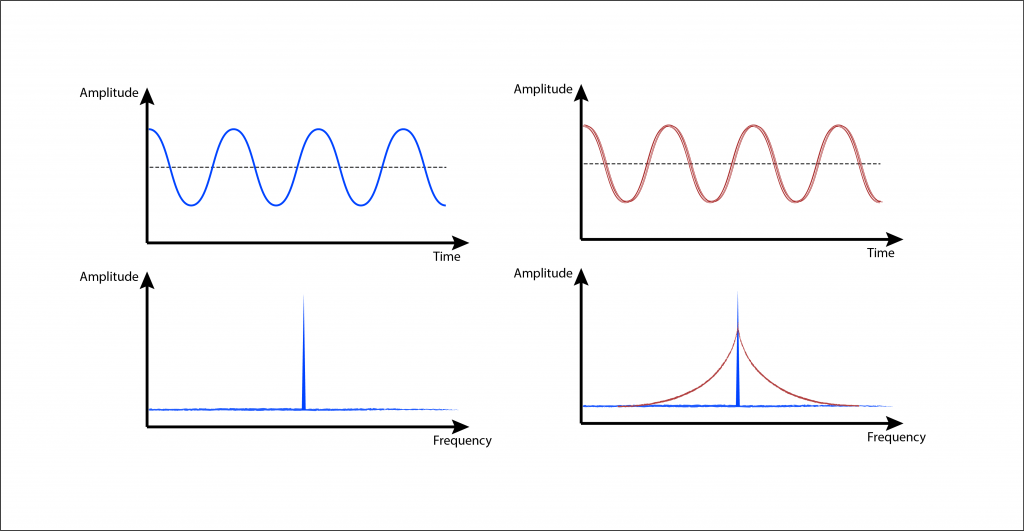
Figure 1: Pictorial depiction of Phase fluctuations in real oscillator: (Left side) Ideal oscillator signal along with its freq. spectrum (Right Side) Noisy oscillator’s signal along with its freq. spectrum
2) How Phase Noise affects Communication systems?
LO Phase-Noise gives rise to (a) Spectral-Regrowth in Transmitters (b) Reciprocal Mixing in Receivers and (c) Constellation rotation of Digital Modulations, degrading the performance of communication systems.
(a) Spectral Regrowth in Transmitters
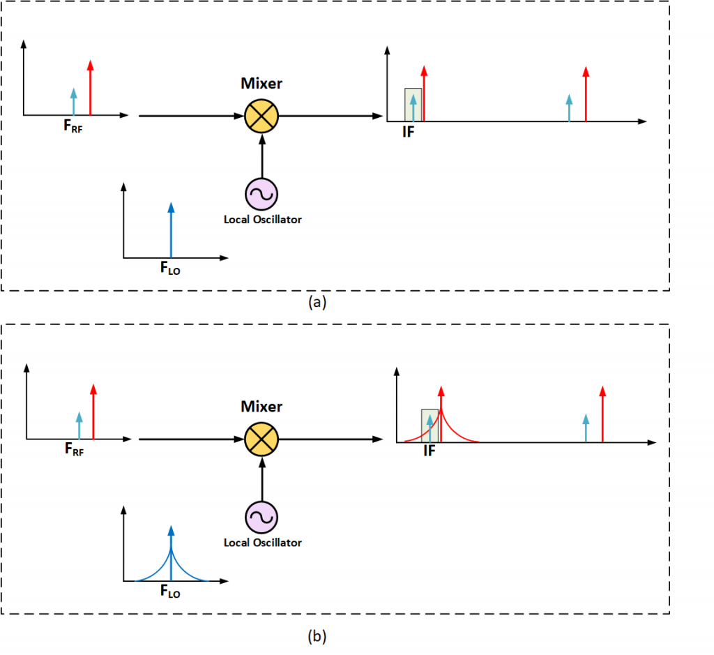
To formulate the basis of our discussion, let’s understand the basic functionality of a mixer in RF systems before going into Phase-noise effects. A mixer is a three-port device used for frequency translation (either down-conversion or up-conversion). An ideal mixer takes up two input signals (fin and fLO) and outputs the sum and difference of input signals, however, a real mixer also produces higher-order products too. Figure 2(a) represents mixing phenomenon assuming that LO is clean and noiseless, while Figure 2(b) presents a real case with noisy LO where mixer output gets modulated with LO Phase noise causing spectral regrowth issues in RF transmitters.

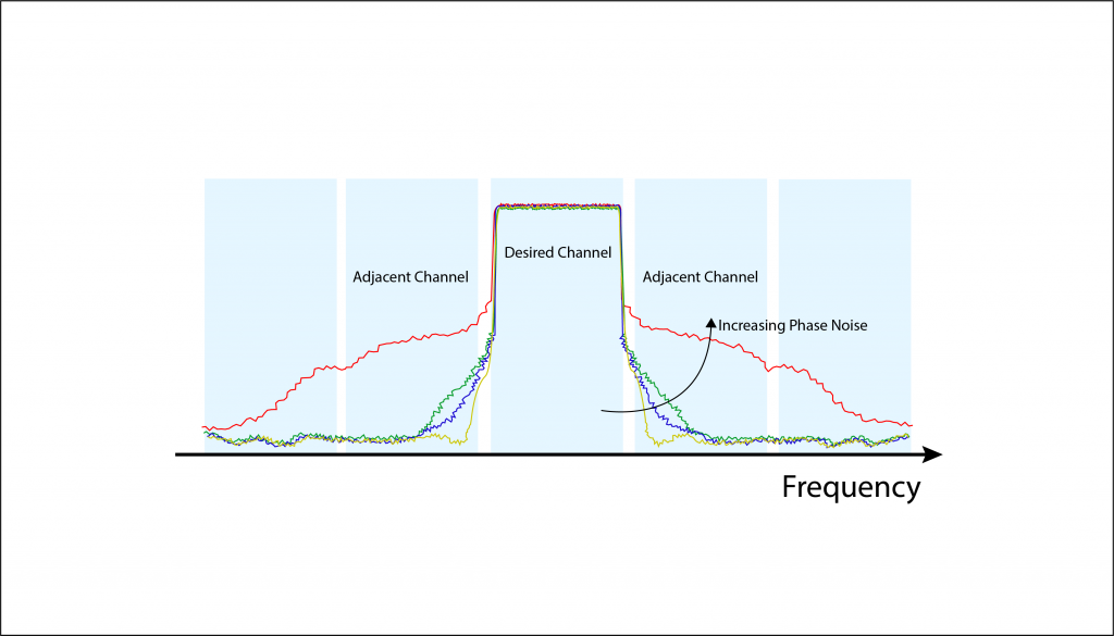
This spectral regrowth give rise to adjacent channel leakage problem in transmitters as shown in Figure 3. It can be observed that as the LO Phase noise increases, more and more power get leaked into adjacent channels for a typical modulated signal.
(b) Reciprocal Mixing in Receivers
After discussing how Phase-noise degrades transmitter’s performance, let’s move on to receiver and see how it gets affected by Phase-noise. Figure 4 presents a typical receiver scenario where a large-blocker (shown in red) is intercepted by RX antenna in close-proximity of weak desired signal (shown in green). Figure 4(a) shows the case if LO were noiseless and suggests that receiver would have decoded desired signal correctly. However, Figure 4(b) clearly explains that receiver sensitivity degrades as the desired signal gets swamped by phase-noise of close-in interferer. This phenomenon is called Reciprocal Mixing in Receivers.
(c) Constellation ‘Rotation’ of Digital Modulations
Next, we will examine another typical impairment, caused by LO Phase Noise, in digital communication systems. To start with, let’s have a brief introduction to constellation diagram. A constellation diagram is nothing but a phasor representation of digitally modulated data where each symbol is characterized by a specific magnitude as well as phase on a complex-plane. For instance, constellation diagram of 16-QAM is shown in Figure 5 as a reference where each symbol is denoted by a separate ‘point’ on constellation diagram featuring unique Amplitude and phase.
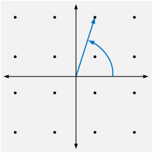
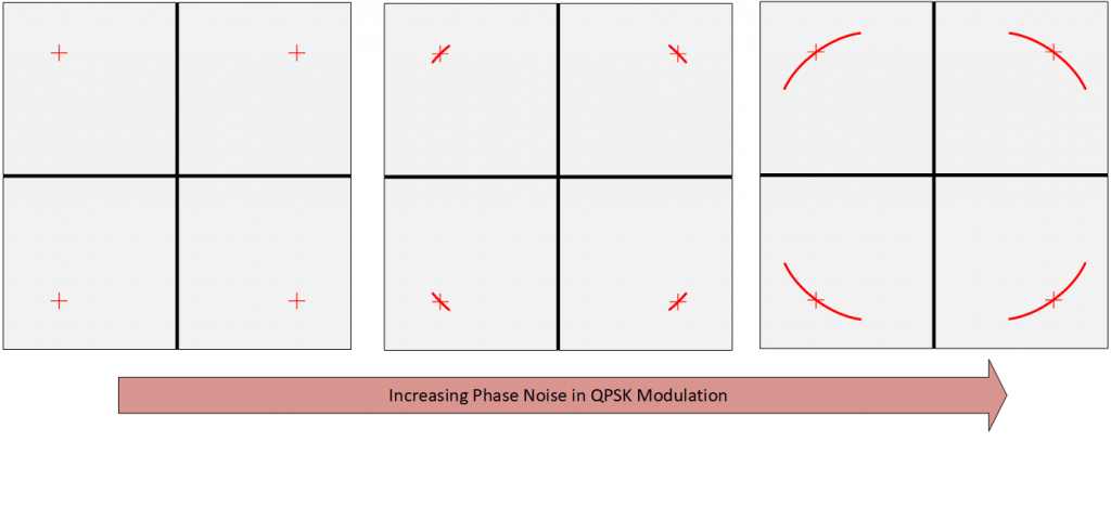
Ideally, transmitter and receiver are desired not to disturb the constellation points to decode the transmitted information at RX without errors. However, LO phase-noise doesn’t let this happen and introduces a so-called rotation in constellation diagram causing increased BER. As shown in Figure 6, Phase noise forms an arc like dispersion around the constellation points by introducing noise in the phase of each point. So, the boundary regions get closer to each other on constellation diagram increasing the BER of communication link. Please be reminded that there are other factors too that deteriorates constellation, however, we have specifically discussed one related to Phase-Noise.
If you want to learn further types of constellation-distortions and how visual inspection of constellations can help identifying the error-sources in an RF system, read this article: Understanding ‘Constellation-Distortions’
So far, we have discussed first two questions that were posed at the start of the blog. In the next post, we will talk about question 3. Stay tuned with us!


