Drawbacks of Direct Conversion receivers – Flicker Noise Penalty Example
How do RF Front-End components effect the Flicker Noise Penalty?
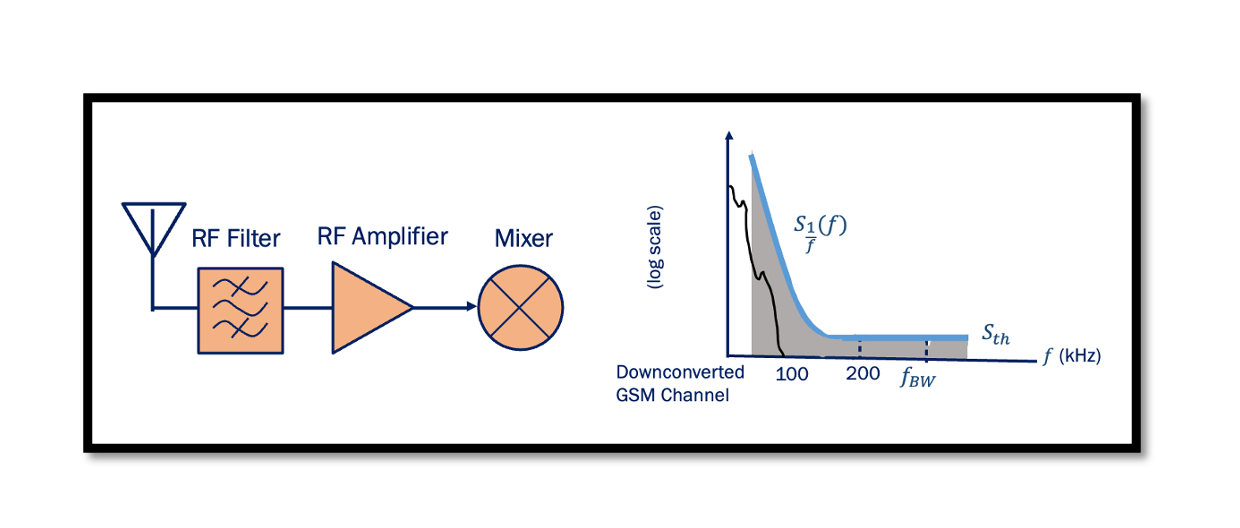
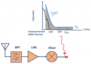
We will first discuss the effect of the Antenna, LNA, and Mixer on the Flicker Noise Penalty then use an example to show if it’s good or bad for the system. Let’s start with thermal noise, the front end of a radio frequency circuit consists of these components: bandpass filter, LNA and Mixer. The Front End (FE) is a generic term for the circuit between the antenna up to and including the mixer block. So, first, we have the antenna which intercepts the electromagnetic radio waves, and this antenna has thermal noise, then there is a bandpass filter, LNA, and Mixer which has noise as well as gain. When we talk about the spectrum in the below diagram it means we are observing the spectrum after the mixer which down converts. So what we are saying is the channel is down-converted and as shown in the diagram we have thermal noise (Sth thermal noise PSD). The source of this thermal noise is the antenna, BPF, LNA, and mixer. Most of all it is because of the antenna, LNA, and mixer, as in BPF the amount of thermal noise is very less and can be ignored. The amount of thermal noise rises at the end of the baseband chain, mostly because of noise from these three components; antenna, LNA, and mixer.
Higher front-end gain directly rises the thermal noise. LNA and Mixer have gain and with higher gain, the noise from the antenna gets amplified. If this is good or bad for our system let’s find out using an example:
How much gain must precede the given noise spectrum so that penalty remains below 1dB?
The higher the LNA and mixer gain, the higher the thermal noise and higher PSD. In this example we will find how much gain must precede the given noise spectrum (we are talking about the gain of front end) so that the penalty remains below 1dB.
We are going to solve this for a new system so let’s assume that we had a gain previously and for this previous system the flicker noise penalty (Pn1/Pn2) is equal to say 16. For the new system, Pn1/Pn2 should be less than 1dB means less than 10. So we will be seeing the effect of gain here.
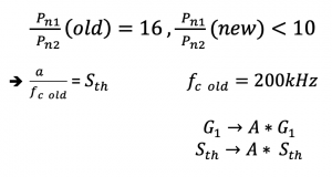
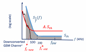
Now for the new system, we are going to increase the gain because we have to decrease the penalty and the only way is to increase our gain. Let the old system gain be G1 so for the new system, the gain would be A*G1 (we are increasing the gain with value A). How does it affect the thermal noise? so if we had a thermal noise for the old system, in the new system the thermal noise will be A*Sth, if we increase gain, we are also increasing the thermal noise.

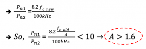
The value of Pn1/Pn2 should be less than 10. So if we calculate further, we can see that as a result, A should be higher than 1.6. The numbers are not important here the importance of this example is to show how the gain of the front end affects the flicker noise penalty. The gain needs to be increased 1.6 times the old system gain.
For instance, if the gain for old system was 10, with this gain we can’t reach this kind of penalty, so we have to increase it 1.6 times and make it 16dB to get the penalty less than 10. The important point to note here is we always have to increase the gain of the front end to have lower penalties, so we say a higher gain means a lower noise penalty.

Learn more about this topic by taking the complete course ‘RF System Design of Receivers, Transmitters & Transceivers – RAHRF409’. Watch the course videos for more detailed understanding. Also checkout other courses on RF system and IC design on https://rahsoft.com/courses/.
Rahsoft also provides a certificate on Radio Frequency. All the courses offer step by step approach.


