Understanding 90˚ Phase Shift and Hilbert Transform
90 degree Phase Shift – Quadrature Down Conversion
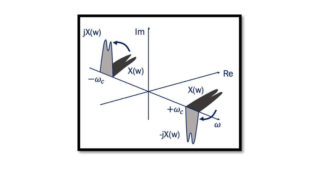
When a signal becomes its own image it corrupts the desired channel and the solution to this problem is Quadrature Down Conversion. Read more about the Image problem. The below plot shows the effect of a 90˚ phase shift on a narrowband modulated signal. It shows what happens when we do a 90˚ phase shift to the spectrum in time domain. In the below equation, we have the cosine and after we do the phase shift of this cosine, we get the sine. In the frequency domain, the cosine wave has two real parts and no imaginary part; however, the sine wave has imaginary parts with opposite signs. The image below is the original narrowband modulated signal and after phase shift, the spectrum translates. This can be shown in the frequency domain as well. So we have our channel, and we do the same thing that is 90 degrees rotation clockwise and 90 degrees anticlockwise to reach the other signal and these two signals are called quadrature signals. These quadrature signals are used in order to solve the image problem that we faced in the zero-IF receiver.

What is Hilbert Transform?
The shift by 90˚ operation that we just discussed above is called Hilbert Transform. When for a spectrum the phase angle shifts +90˚ for the negative frequency components and -90˚ for the positive frequency components, the resultant signal in time domain is the Hilbert Transform.
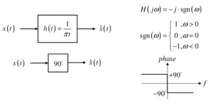
The method used here is the positive frequency contents are multiplied by -j, and it gets translated 90˚ clockwise. The negative frequency contents are multiplied by +j, in this kind of transform as shown spectrum shifted anti-clockwise. The shift by 90˚ operation is called the Hilbert transform. The function of the Hilbert Transform is shown below. The impulse response of the Hilbert Transform h(t) = 1/πt.

Hilbert transform is a linear operator that produces a different variable of a given function, given by convolution with 1/πt. The If we find the Fourier transform of the signal, it would be -j.sgn(ω). Hilbert transform does not involve domain change. As shown in the Figure Hilbert Transform results in a different signal in the same domain, the only change involved is the phase change.
Example of Hilbert Transform
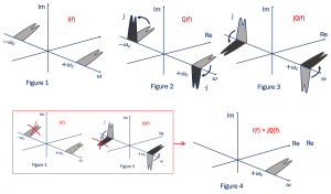
In the given plot Figure 1, the Narrowband Signal I(t) is shifted by 90˚ to produce Q(t). In this example plot I(f)+jQ(f).

This is the original signal I(f) and we do a 90˚ phase shift to get Q(f). Now we multiply with +j and -j to get the imaginary 90˚ parts. So what about the jQ(f), when the -j multiplied by j becomes 1 it’s a real value, and it comes back to the same position (Figure 3), but the other side becomes -1. Finally when we add it together (Figure 1 & 3) that is I(f)+jQ(f) we can see one side is cancelled out, this is because they have the exact same value with the negative sign so it will be cancelled, and we only have one part left here as shown in Figure 4.


