Drawbacks of RC-CR Network
What are the drawbacks of using RC-CR network?
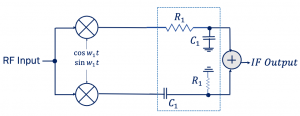
RC-CR Network is one of the methods to implement a 90-degree phase shift in a receiver. In this blog, we will discuss the drawbacks of using this method.
1. Image rejection might degrade near the edges of a channel for wide channel bandwidth.
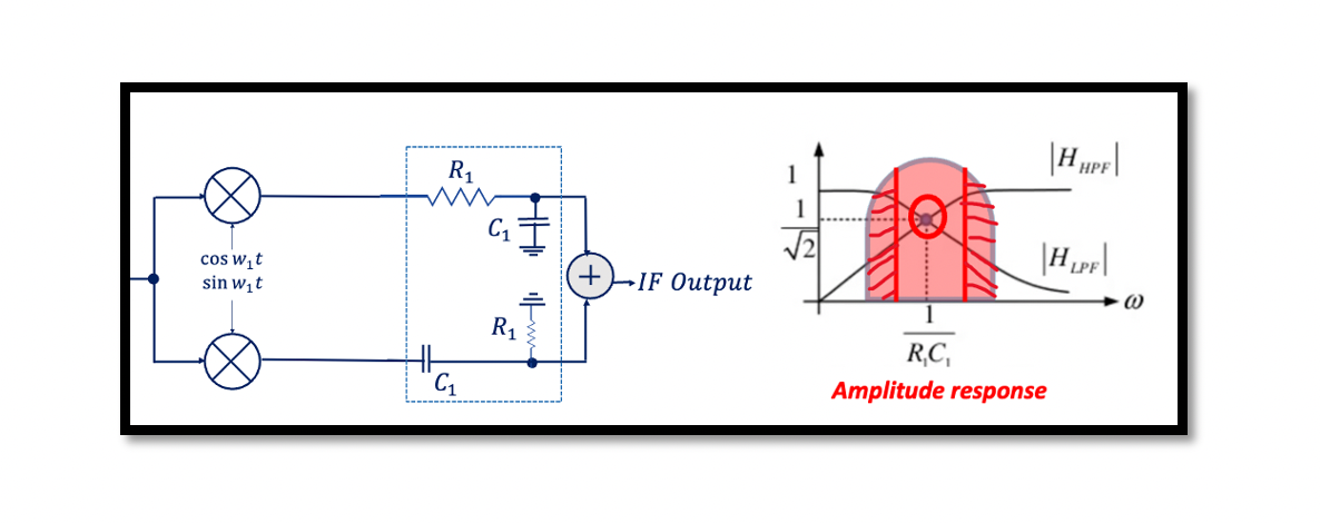
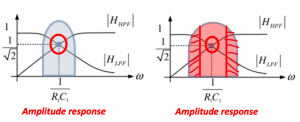
If a channel has wide bandwidth there will be a problem with image rejection. Since the gain of low-pass and high-pass sections departs from each other as frequency departs from (R1C1)-1, the image rejection may degrade near the edges of the channel for wide channel bandwidth.

So what we are trying to explain is when we are getting far from the center frequency (R1C1)-1 the gain of the high pass filter and low pass filter will change, they want to have equal gain so it means that it won’t be a symmetrical structure and we won’t be able to do a proper image rejection. So we always have to use a narrow channel bandwidth, hence this RC-CR structure is appropriate for narrow channels.
2. R and C variations cause the gain error
What we assume is that there is the same gain for high pass and low pass filters and the ratio equals one to have a proper image rejection, however, that’s not what happens in the real scenario. We have variations in R and C which get added and lead to a mismatch. So the gain of these two filters will differ which will ultimately cause the image rejection problem.

3. When there is attenuation (gain<1) -> Noise of the adder is amplified
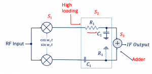
The gain in the RC-CR network is less than 1 which leads to an increase in the noise of the adder. This structure below is a cascaded stage: stage 1, stage 2, and stage 3. What will be the noise contribution of the adder in the below structure? The noise of each stage will be divided by the gain of the preceding stages, which means when we want to observe the noise of this adder, calculate the noise figure of this adder. So, the noise figure of this adder will be divided by the gain of the previous stages which means the gain of the RC-CR network. If you calculate using the noise figure formula then you will see the noise contribution of the adder; when the gain decreases the overall noise of the adder increases, and that’s the drawback. We have attenuation, less gain, and hence the noise of the adder gets amplified (gain <1).
4. The trade-off between the thermal noise of RC-CR and mixer loading
The mixer loading is coming from this RC-CR network and we want to have high loading it means if we decrease the loading there will be a problem in the mixer, and the gain of the mixer will decrease. See the below structure.

So the output resistance/ impedance should be high so the mixer can have proper gain. The trade-off here is, when the value of resistance increases the noise also increases in the circuit, it’s the thermal noise that increases here. So it’s a trade-off we want to increase the R to have a proper operation of the mixer the thermal noise increases and vice versa.


