How to implement 90 degree phase shift in Hartley Receiver
As discussed in the previous blog about the methods to implement 90˚ phase shift, the first method was RC-CR network and second method was quadrature down conversion.
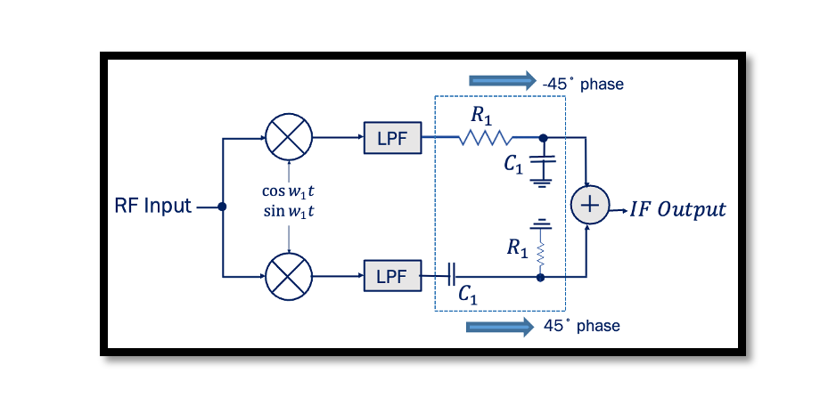
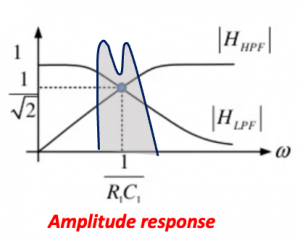
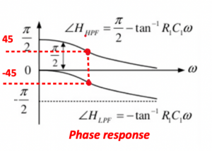
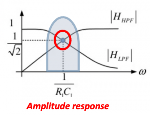
In the below figure the architecture of Hartley receiver shows that instead of having 90˚ phase shift at one end we are having 45˚ and -45˚ phase sift both sides, hence in total the two signals will have 90˚ phase difference. Looking at the amplitude response for this we can see that two signals produced have same amplitude operating around 1/R1C1. There will be little attenuation but its the same for both sides so the amplitude will be same. The phase response shows at exactly 1/R1C1 the phase difference is 90.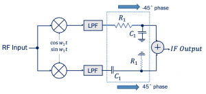
Drawbacks of Hartley Architecture
One of the drawbacks of this architecture is mismatch. Read about mismatch. The Hartley receiver structure is sensitive to mismatch. In short, when there is error in the 90˚ phase shift circuit and mismatches between the quadrature mixers, it results in imbalances in amplitude and phases of baseband I and Q outputs and the data cannot be completely restored properly and therefore, we will have data errors. 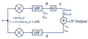
What kind of mismatch we will have in Hartley architecture?
- LO phases are not in exact quadrature
- Gain and phase shift of two paths are not identical.
We always want to have 90˚ phase shifts in these mixers to produce the cosine and sine waves but due to mismatch it won’t be exactly 90˚, it can be more or less. At this point there will be a phase difference ∆Ø.
If the systems are not identical and precise there will be gain and phase error. To quantify it, the mismatches of the receiver are lumped as single amplitude error ε and phase error ∆Ø.
To make it easier to understand we have implemented amplitude and phase error in one side instead of having it on both sides as shown below. As shown using the equations, when we add them we get signal output (xsig,out) and image output (xim,out), which shows that due to mismatch the image cannot be completely removed. Assume there is no mismatch, the phase and amplitude error equals 0 then it cancels out and there is no image problem. However, in real world that’s not possible, as systems are not precisely identical, there will always be a little bit of mismatch leading to image problem. In order to see how much we were successful in rejecting the image we have to define the measure which is called IRR or image rejection ratio.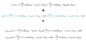
What is Image Rejection Ratio (IRR) and calculate image rejection ratio
This measure is to find out how much our image is attenuated. It is equal to the ratio between the power of image and power of signal and we want to minimise this to minimise the power of image. This equation is calculated using the signal and the image output equations. When we talk about power it means average power. Read about average power and how to calculate it here.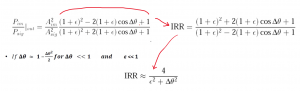
For example, ε=10 (≈0.83 dB) limits the IRR to 26 dB. Similarly, ∆Ø = 10˚ yields an IRR of 21 dB. While such mismatch values may be tolerable in direct-conversion receivers, they prove inadequate here. so we really have to be careful about the mismatch, need a precise design for image rejection receiver and this is one of the main problems.
Drawbacks of using RC-CR network
We assume that we have constant value for R1 and C1 but that not always the case. We have variations of these values. There will be mismatch because of this process variation.
- Variation of the absolute values of R1 and C1.
- (R1C1)-1 = wIF, if system experiences a small change of ∆R and ∆C with process or temperature, then:
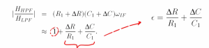
For example our resistance is 100 ohms but when we send out a chip to the fabrication it becomes maybe 90 ohms, so this is a variation process variation and we will have mismatch because of this. We also assumed that the gain and phase response of high pass filter is equal to low pass filter but as we can see there is a small change in resistance and capacitance we will have gain difference, so the ratio is not equal to 1 anymore.
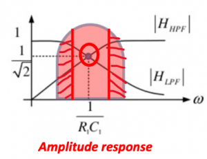
- Since the gain of low-pass and high pass section departs from each other as frequency departs from (R1C1)-1 = wIF the image rejection may degrade near edges of channel for wide channel bandwidth.

Learn more about this topic by taking the complete course ‘RF System Design of Receivers, Transmitters & Transceivers – RAHRF409’. Watch the course videos for more detailed understanding. Also checkout other courses on RF system and IC design on https://rahsoft.com/courses/. Rahsoft also provides a certificate on Radio Frequency. All the courses offer step by step approach.
You may also like
Understanding Quadrature Amplitude Modulation (QAM) and Its Applications