How does the image rejection receiver work?
Image rejection using Hartley Architecture
This blog talks about how Hartley architecture uses 90-degree phase shift and quadrature down conversion to remove the image. In previous blogs, we discussed about 90˚ phase shift, Quadrature down conversion, and image problems.
Hartley Receiver is one of the most popular structures for image rejection receivers.
The architecture below shows quadrature down-conversion with a 90˚ phase shift, now we have our channel with the image shown below. First, we find the frequency of the local oscillator which is shown using the red arrow in the middle of the channel and image (wLO and -wLO).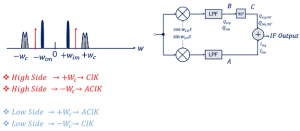
Let’s start with down conversion and see the signals at points A and B.
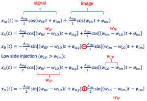
For the cosine part, we just don’t need any formula because it’s going to be translated to wIF. For the sine part, we will be using the formulas that we discussed in one of our previous blogs: High and Low Injection – Implementing 90˚ Phase shift
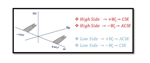
Check for the high and low-side injections using the formula.
For Qsig: From the diagram, we can see that wLO<wc so the signal Qsig is on the low side. Low side it rotates anticlockwise (AClK) from the formula. This is the signal after the mixer (sin wLOt) and low pass filter (LPF). The high-frequency components are removed by LPF, as we have already shown using the equation in the aforementioned blog.
For Qim: For image signal Qim the wLO>wim. So, we have a high-side injection according to the formula. This means high side, the wc turns clockwise (ClK).
For the cosine parts (Isig&Iim) it will be translated to the IF frequency.
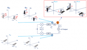
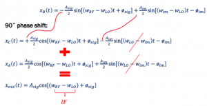
Now let’s see what is happening to the channel after the 90˚ phase shift at point C.
In a 90-degree phase shift, there is only a pattern, unlike high and low injection. Its always clockwise at the positive side and anti-clockwise at the negative side, as represented in the figure below which shows the changes from point B to C:
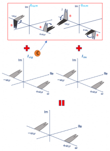
So now we have reached a point where C and A have to be added. let’s see what is happening here:
You can notice that Qim,90˚ is exactly opposite to Iim, so when we added these together, it will get cancelled and there will be no image signal. This is how the image rejection receiver works The point here is that we are trying to play with signals to make the polarity of the image exactly opposite to the polarity of the image at the other point and doing so when we add it together the image cancels out and hence, we get rid of the image using this architecture.
This method can be proved using analytical expression as well as shown in the next paragraph. We have also explained this topic in a detailed way in our course. You can learn using the video tutorial: ‘RF System Design of Receivers, Transmitters & Transceivers – RAHRF409’
Example – Hartley Architecture Image Rejection

