Implement 90-degree phase shift – Weaver Receiver Architecture
Weaver Receiver Architecture
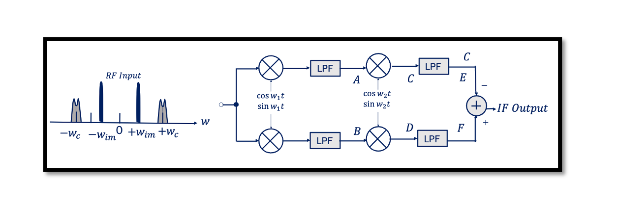
In this blog, we will discuss about Weaver Architecture. This structure is used for image rejection. Previously we discussed about Image rejection using Hartley Architecture. Weaver architecture is similar to Hartley Receiver, this structure uses quadrature down conversion for the first part. If we recall from a previous blog about the RC-CR network, which uses two filters, the high pass filter (CR) and the low pass filter (RC) where we do 90˚ phase shift, but because of the problems we faced, the drawbacks that we discussed about RC-CR network we are not going to use this method. There are two methods to implement a 90-degree phase shift inside a receiver. The first method is the RC-CR network, and the second method is quadrature down conversion which is a preferred method. Quadrature down conversion translates the spectrum to a non-zero IF as a 90˚ phase shift. Creating two versions of a down-converted signal that have a phase difference of 90. Instead of RC-CR Network, we are going to use quadrature down conversion for the second part as well. Read about How is the 90˚ phase shift implemented? Let’s see what is happening to our signals:
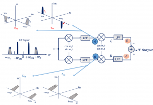
We have low side injection for sine parts meaning our signal (Qsig) will turn anti-clockwise for a positive frequency and clockwise for a negative. For image (Qim) we have high side injection so the positive frequency will turn clockwise and anti-clockwise for the negative side.
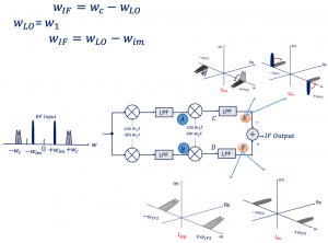
For cosine, we don’t have any imaginary parts, it’s only real parts so there will only be a frequency shift to wIF. What is wIF here?

At this point, we are assuming that for the second part we have a low-side injection as well. Now the channel and image are happening at the same frequency of wIF. The channel and image are at the same frequency so both will experience the low-side injection. As shown in the above image for the cosine part its again the real parts only, no image (Isig and Iim). It’s not zero IF as you can see. Here we are having a secondary IF and we are going to intermediate frequency, not to baseband.

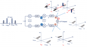
At point E, we will have the same rotation as the previous part as its low side injection for both channel and image. But we cannot add these together unlike in Hartley architecture because it results in cancellation of the channel instead of image. The only choice is to change the polarity of the adder by putting negative (-), look at the image below what happens when we change the polarity, the Qsig and Qim changes to exactly opposite as it was and now we can add them together and at the output we have our channel. However, there is drawbacks to weaver architecture as well which we will be discussing in next blog.


