Wave Propagation in Transmission Line
In the previous blogs, we discussed transmission line time domain equations using the phasor formula. In the first case assuming there is no reflection we showed wave propagation and second case we showed the condition of the standing waves when there is a reflection using the phasor equation.
- Case 1: Example to prove wave propagation
- Case 2: Transmission line Reflection Equation
What is Wave Propagation in Transmission Line?
Wave propagation in a transmission line refers to the movement of an electromagnetic wave along the line. When a voltage is applied to the input of the transmission line, an electromagnetic wave is generated that travels along the line, carrying energy and information.
The direction of wave propagation is determined by the polarity of the voltage applied to the transmission line. If the voltage is positive at the input end of the line, the wave travels in the positive z direction (+z), which is from left to right. Conversely, if the voltage is negative at the input end of the line, the wave travels in the negative z direction (-z), which is from right to left.
For example, suppose we have a coaxial cable with a positive voltage applied to the input end of the cable. The electromagnetic wave generated by the voltage travels in the positive z direction, which is from left to right. As the wave travels along the cable, it induces an electric field and a magnetic field that vary with time and propagate along the line.
If the characteristic impedance of the cable is matched to the source and load impedances, the wave will travel along the line without any significant reflection or loss of energy. However, if there is a mismatch in the impedance, some of the energy will be reflected back to the source, resulting in signal distortion and loss.
In summary, wave propagation in a transmission line refers to the movement of an electromagnetic wave along the line, carrying energy and information. The direction of wave propagation is determined by the polarity of the voltage applied to the line, with positive voltages causing the wave to travel in the positive z direction (+z) and negative voltages causing the wave to travel in the negative z direction (-z). Matching the characteristic impedance of the line to the source and load impedances is crucial for efficient transmission of signals.
Example to show Wave Propagation
We derived the phasor formula for our transmission line in the blog transmission line phasor equations. This is the phasor equation (1) shown below assuming that there is no reflection.
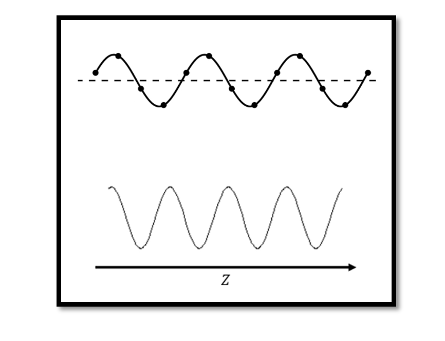
The second part of equation (1) is our reflection showing the wave propagation in the -z direction (opposite direction). If you assume that +z is from the left to the right direction shown using the axis in the below figure, when we see this kind of wave there is no reflection.
We proved this wave propagation using equation (2) in Transmission Line Time Domain Equations. The equation (2) is for a lossless transmission line where ? = 0. Finding the cosine wave (for example t1, t2, t3…) for each time we are going to see that this wave is shifting from left to right which proves that the first term of equation (1) is showing wave propagation in the positive direction (+z). Each time the value of t changes the wave shifts to the right side. This is called wave propagation.
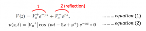
If you convert the second part of the equation (1) which is nothing but (wt-ßz), so changing the value of t=1, 2, 3…. You will see that the wave is shifting from the right to the left side which is the opposite direction (-z). The waves shown below are called flat waves because the amplitude remains constant. It remains between Vmin and Vmax which are the peak points, also the distance between the two peak points of the wavelength remains constant. The condition here is when it satisfies no reflection.
Also, check out the blog where we showed Examples to prove wave propagation using the time domain equation.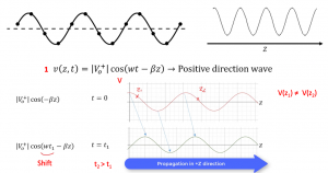

Learn more about this topic by taking the complete course ‘RF Microwave and Radio Frequency Transmission Theory Online Course – RAHRF200’. Watch the course videos for more detailed understanding. Also checkout other courses on RF system and IC design on https://rahsoft.com/courses/. Rahsoft also provides a certificate on Radio Frequency. All the courses offer step by step approach.
You may also like
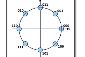
Understanding Quadrature Amplitude Modulation (QAM) and Its Applications