Connection between Power Gain, Available Power Gain, and Transducer Power Gain
Transducer Power Gain and Available Power Gain
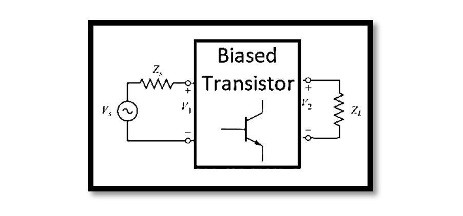
Transducer Power Gain and Available Power Gain are two fundamental concepts in evaluating the efficiency of power transfer within networks. Available Power Gain (GA) serves as a crucial metric, representing the efficiency of power delivery within a network. It is essential to grasp its equation and significance for optimizing system performance. Available Power (PAV) denotes the maximum power that can be transferred to the load (ZL), reflecting the network’s power delivery efficiency. On the other hand, Transducer Power Gain (GT) quantifies the effectiveness of power transfer from the source to the load through the transducer. It is expressed as the ratio between the power delivered to the load (PL) and the available power at the source (PAVS). Both PAVS and PAVN play pivotal roles in elucidating the maximum power transfer capability of the system. Understanding these definitions provides a solid foundation for optimizing power transfer efficiency within networks, ultimately enhancing overall system performance.
Connection between Power Gain, Available Power Gain, and Transducer Power Gain
Power Gain, Available Power Gain, and Transducer Power Gain are interconnected parameters crucial in assessing the efficiency and performance of electrical networks. Available Power Gain (GA) represents the efficiency of power transfer within a network, defined as the ratio of the available power at the load to the available power at the source. It is calculated using the equation:

where PAVL is the available power at the load and PAVS is the available power at the source. Transducer Power Gain (GT), on the other hand, measures the effectiveness of power transfer from the source to the load through the transducer. It is expressed as the ratio of the power delivered to the load to the available power at the source:

where PL is the power delivered to the load. Power Gain (G) is related to both Available Power Gain and Transducer Power Gain through the equation:

This equation demonstrates that Power Gain is the product of Available Power Gain and Transducer Power Gain, illustrating their combined impact on the overall efficiency of power transfer within the network. Understanding this relationship is crucial for optimizing network performance and ensuring efficient power delivery.
Example: Calculation of Power Gain for a Silicon Bipolar Junction Transistor (From Microwave Engineering, David Pozar)
Consider a silicon bipolar junction transistor operating at a frequency of 1.0 GHz with a reference impedance of 50 ohms.
The transistor exhibits the following scattering parameters:

The input impedance (Zs) of the transistor is 25 ohms, and the load impedance (ZL) is 40 ohms.
We are tasked with calculating the power gain (G) of the transistor using the given scattering parameters and impedance values.
Let’s proceed with the calculations. Calculate Γs and ΓL using the provided formulas:

Substitute the values:


In conclusion, the relationship between Power Gain, Available Power Gain, and Transducer Power Gain forms the cornerstone of efficient power transfer within electrical networks. Available Power Gain (GA) serves as a metric for assessing the effectiveness of power delivery within a network, reflecting the ratio of available power at the load to that at the source. Transducer Power Gain (GT) quantifies how effectively power is transferred from the source to the load through the transducer. These parameters are interconnected, with Power Gain (G) representing the combined impact of Available Power Gain and Transducer Power Gain. Understanding this interplay is crucial for optimizing network performance and ensuring efficient power delivery. By comprehending the equations and significance of these metrics, engineers can design and optimize electrical networks to achieve maximum power transfer efficiency and enhance overall system performance.

Learn more about this topic by taking the complete course ‘Microwave Amplifier and Low Noise Amplifier (LNA) Design Theory and Principles online course – RAHRF526’. Watch the course videos for more detailed understanding. Also checkout other courses on RF system and IC design on https://rahsoft.com/courses/. Rahsoft also provides a certificate on Radio Frequency. All the courses offer step by step approach.


