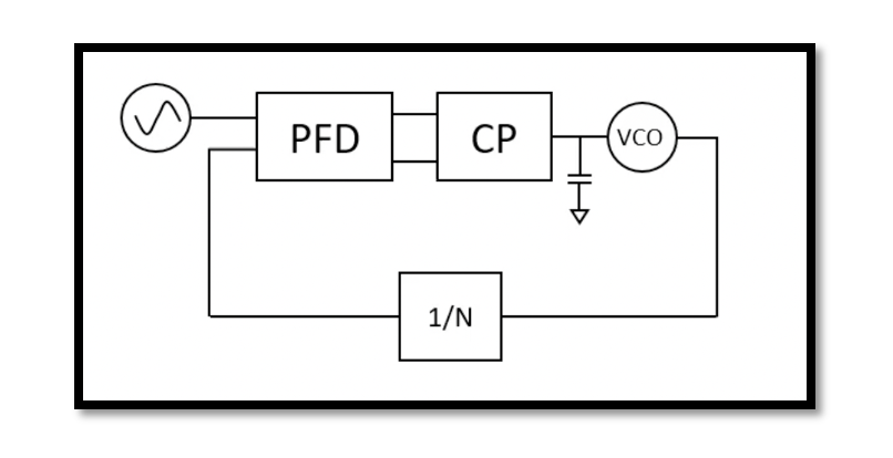
What is Phase-Locked Loop?
A Phase-Locked Loop (PLL) is a sophisticated electronic control system that aligns the phase of an output signal with a reference input signal through a feedback loop, ensuring their frequencies match. It consists of a phase detector, a low pass filter, and a voltage-controlled oscillator (VCO). The phase detector compares the phase difference between the input signal and the VCO’s output, generating a corresponding error voltage. This error voltage is then filtered by the low pass filter to remove noise and produce a smooth control signal.
The control signal adjusts the VCO’s frequency to reduce the phase difference, effectively “locking” the VCO’s phase to the reference signal. This feedback mechanism allows the PLL to stabilize and track the input frequency, even in the presence of noise and other perturbations. The VCO’s susceptibility to temperature variations and other environmental factors is mitigated by the PLL, ensuring a stable and precise output frequency. PLLs are integral to numerous applications, including frequency synthesis in communication systems, clock generation and recovery in digital circuits, and modulation and demodulation processes in signal processing. Their ability to generate high-frequency signals from lower-frequency references and reduce phase noise and jitter underscores their importance in maintaining signal integrity across various electronic and communication devices.
In short, a phase-locked loop (PLL) is a versatile feedback control system widely used in electronic circuits for a variety of applications, including frequency synthesis, modulation, demodulation, and clock generation. Here’s a more detailed explanation of its components, functionality, and applications, along with relevant equations:
Components of a Phase-Locked Loop
- Phase Detector (PD) or Phase Comparator:
- Compares the phase of the input signal with the phase of the signal from the Voltage Controlled Oscillator (VCO).
- Outputs a voltage that represents the phase difference between the two signals.
- Low Pass Filter (LPF):
- Filters the output of the phase detector to remove high-frequency components and noise.
- Produces a smooth control voltage to adjust the VCO.
- Voltage Controlled Oscillator (VCO):
- Generates an oscillating signal whose frequency is controlled by the input voltage (from the LPF).
- The output frequency of the VCO is fed back to the phase detector.
- Feedback Loop:
- Ensures the system maintains a constant phase angle between the input signal and the VCO output.
How PLL Works
- Phase Detection:
- The phase detector compares the input reference signal with the VCO output. If there is a phase difference, it generates a corresponding error signal.
- Error Signal Filtering:
- The low pass filter smooths the error signal, producing a control voltage proportional to the phase difference.
- Frequency Adjustment:
- The control voltage adjusts the VCO frequency. If the VCO frequency is too high, the control voltage decreases, and if too low, the control voltage increases.
- Locking Process:
- The VCO frequency is adjusted until the phase difference is minimized, effectively locking the output signal phase to the input signal phase.
Take our entry level course (Below) for free using coupon code RAHRF101BLOG
RF Fundamentals, Basic Concepts and Components – RAHRF101
For limited time take an additional 10% off of all our courses using coupon code RFCERT10
Rahsoft RF Certificate and courses
Key Equations
- Phase Detector Output:
VPD=Kd⋅ϕe
where VPD is the phase detector output voltage, Kd is the phase detector gain, and ϕe is the phase error.
- Low Pass Filter Transfer Function:
Vcontrol(s)=H(s)⋅VPD(s)
where 𝐻(𝑠)H(s) is the transfer function of the low pass filter.
- VCO Frequency:
fVCO=f0+Kv⋅Vcontrol where fVCO is the output frequency of the VCO, f0 is the free-running frequency of the VCO, Kv is the VCO gain, and Vcontrol is the control voltage.
Applications of PLL
- Frequency Synthesis:
- PLLs can generate high-frequency signals from a lower frequency reference, essential in RF communication systems.
- Clock Generation and Recovery:
- Used in digital systems to generate stable clock signals and recover clocks from data streams.
- Modulation and Demodulation:
- PLLs can demodulate FM signals by tracking the frequency variations of the carrier signal.
- Jitter Reduction:
- By locking to a reference signal, PLLs can reduce phase noise and jitter in clock signals.
Stability and Noise Considerations
- Temperature Sensitivity:
- VCOs are susceptible to temperature changes, which can alter the oscillation frequency. PLLs compensate for this by adjusting the control voltage to maintain stability.
- Noise Filtering:
- The low pass filter in the PLL helps in filtering out high-frequency noise components, ensuring a stable and accurate output.
In summary, a phase-locked loop is an essential component in modern electronic systems, providing a reliable method for frequency synthesis, signal synchronization, and noise reduction. Its ability to maintain phase and frequency consistency between input and output signals makes it invaluable in various applications.

Learn more about this topic by taking the complete course ‘Phase Lock Loop System Design Theory and Principles RAHRF469’. Watch the course videos for more detailed understanding. Also checkout other courses on RF system and IC design on https://rahsoft.com/courses/. Rahsoft also provides a certificate on Radio Frequency. All the courses offer step by step approach.
Tag:Phase Locked Loop, PLL, VCO


