Understanding and Calculating Phase Margin in Control Systems
Phase margin (PM) is a critical parameter in control system design that indicates the stability of the system. It is the additional phase lag required to bring the system to the verge of instability. In this blog, we will delve into the concept of phase margin, its calculation, and the implications of various system parameters on phase margin.
What is Phase Margin?
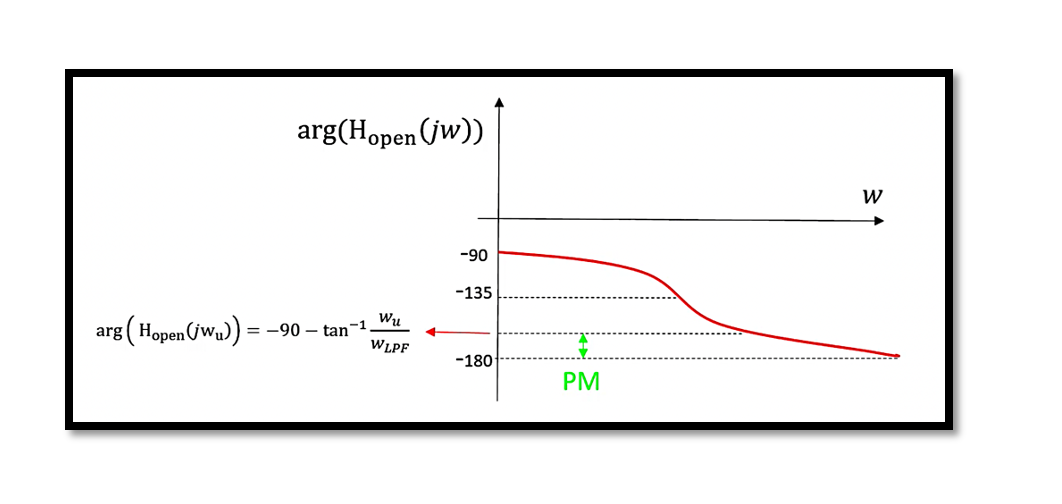
Phase margin is a measure of the system’s robustness to changes in system parameters and external disturbances. It is defined at the frequency where the open-loop gain is unity (0 dB). Mathematically, it is the difference between the phase of the open-loop transfer function and -180° at the gain crossover frequency (the frequency where the magnitude of the open-loop transfer function is 1).
Calculating Phase Margin
To calculate the phase margin, follow these steps:
Determine the Open-Loop Transfer Function: Identify the open-loop transfer function 𝐻𝑜𝑝𝑒𝑛(𝑠). For example,

Find the Gain Crossover Frequency: This is the frequency 𝜔𝑢 where

Compute the Phase Margin:

Graphical Representation
A graphical representation helps in understanding how the phase margin is determined. The Bode plot of ∣𝐻𝑜𝑝𝑒𝑛(𝑗𝜔)∣ and arg(𝐻𝑜𝑝𝑒𝑛(𝑗𝜔)) typically shows the gain and phase crossover frequencies. The phase margin can be read directly from the phase plot at the gain crossover frequency.

Summary of Key Points
- Increasing 𝐾𝑉𝐶𝑂 or 𝐾𝑃𝐷 Reduces Stability: Higher values increase the gain crossover frequency, reducing phase margin and potentially causing instability.
- Decreasing 𝜔𝐿𝑃𝐹Increases Ripple: Lowering 𝜔𝐿𝑃𝐹increases the argument tan−1(ωu/ ωLPF ), making the phase more negative and decreasing the phase margin.
- Damping Factor 𝜁: The damping factor also confirms stability trends. It is given by:

Practical Implications
Understanding and managing phase margin is crucial for designing stable control systems. Engineers must carefully balance system parameters to ensure adequate phase margin while achieving desired performance. Tools like Bode plots and transfer function analysis are invaluable in this process.
By adhering to these principles, you can ensure your control systems are robust, stable, and perform well under various conditions.
Take our entry level course (Below) for free using coupon code RAHRF101BLOG
RF Fundamentals, Basic Concepts and Components – RAHRF101
For limited time take an additional 10% off of all our courses using coupon code RFCERT10
Rahsoft RF Certificate and courses
Impact of Phase Margin on System Performance
Phase margin directly influences the transient response and robustness of a control system. A larger phase margin typically results in a system that can handle parameter variations and external disturbances more effectively, leading to smoother and quicker settling times with minimal overshoot. Conversely, a smaller phase margin can result in a system that is prone to oscillations and instability, which may cause excessive overshoot and prolonged settling times. This sensitivity to variations highlights the importance of optimizing the phase margin during the design phase to ensure that the control system maintains desired performance levels under a wide range of operating conditions. Properly accounting for phase margin in the design process not only enhances stability but also improves the overall reliability and efficiency of the system.
Conclusion
Phase margin is a fundamental aspect of control system stability. Through careful calculation and consideration of system parameters, you can design systems that are both stable and efficient. Use this guide as a reference to navigate the complexities of phase margin in your control system designs.

Learn more about this topic by taking the complete course ‘Phase Lock Loop System Design Theory and Principles RAHRF469’. Watch the course videos for more detailed understanding. Also checkout other courses on RF system and IC design on https://rahsoft.com/courses/. Rahsoft also provides a certificate on Radio Frequency. All the courses offer step by step approach.
Tag:Phase Margin, PLL


