Introduction to Third Order PLL Filter
Introduction
Phase-Locked Loops (PLLs) are essential components in various electronic systems, especially in communication and signal processing. They are used for frequency synthesis, clock generation, and demodulation. A key part of the PLL system is the filter, which determines the loop’s stability and performance. This blog will dive into the third-order PLL filter, its structure, and its significance.
Higher Order Filter in PLL Systems
The most common filter structure in PLL systems is the higher order filter. This filter design is pivotal because it introduces an additional pole, enhancing the stability and performance of the PLL system. Let’s explore the structure and mathematical representation of this filter.
Filter Structure
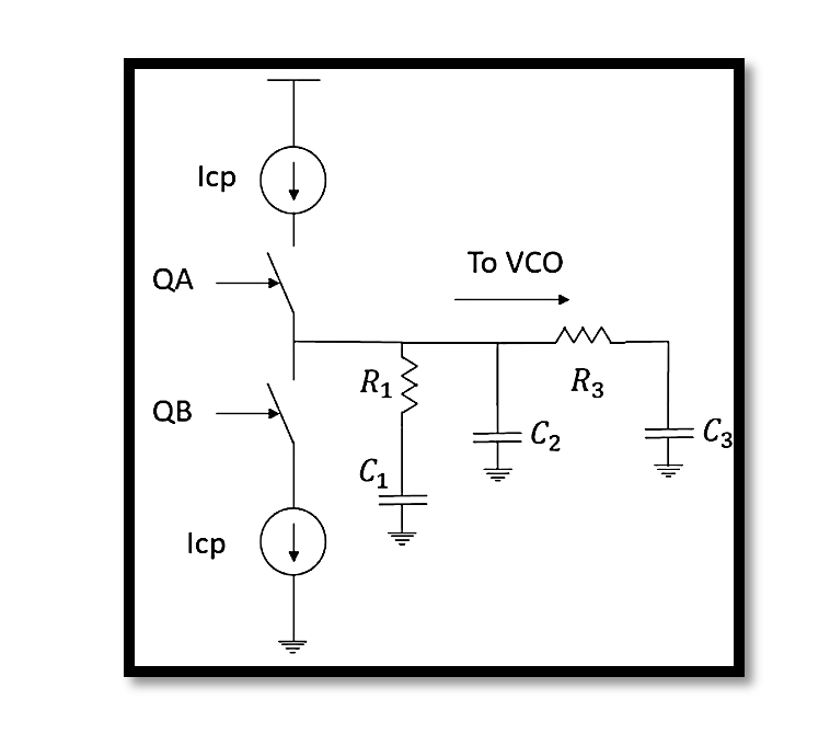
The filter structure, as shown in the diagrams, includes the following components:
- R1, R3: Resistors
- C1, C2, C3: Capacitors
- Icp: Charge pump current
- KVCO: Voltage-Controlled Oscillator gain
The configuration of these components forms a third-order filter, which is a typical choice in PLL systems due to its balance between complexity and performance.
Mathematical Representation
The open-loop transfer function for the PLL with the higher order filter is given by:

Where:
- β is the feedback factor.
- s is the complex frequency variable.
- Wp4, Wp3, and Wu represent the frequencies of the poles and the unity gain frequency.
This equation illustrates how the components interact to shape the frequency response of the PLL.
Detailed Analysis of the 3rd Order PLL Filter
Circuit Description
The third-order PLL filter circuit includes a charge pump (Icp), two resistors (R1 and R3), and three capacitors (C1, C2, and C3). The charge pump feeds into the resistor-capacitor network, which then connects to the Voltage-Controlled Oscillator (VCO). The primary purpose of this network is to filter the control voltage applied to the VCO, ensuring that the PLL locks onto the correct frequency with minimal phase noise.
Additional Pole
An essential feature of this higher order filter is the additional pole introduced by the components R3 and C3. This additional pole plays a critical role in improving the loop’s stability and transient response.
The frequency of the pole introduced by R3 and C3 is:

This relationship indicates that the additional pole is designed to be higher than the unity gain frequency, ensuring that the system remains stable across the desired frequency range.
The notation Wp4≈Wp3>Wu refers to the frequencies of the poles and the unity gain frequency in the context of the third-order PLL filter. Let’s break down what each term means:
- Wp4: This represents the frequency of the fourth pole introduced by the additional components R3 and C3.
- Wp3: This is the frequency of the third pole in the system, which is part of the overall filter design.
- Wu: This denotes the unity gain frequency of the loop, which is the frequency at which the magnitude of the open-loop gain is unity (0 dB).
The relationship Wp4≈Wp3>Wu means:
- Approximate Equality of Pole Frequencies: Wp4≈Wp3 indicates that the frequency of the fourth pole (introduced by R3 and C3) is approximately equal to the frequency of the third pole. This suggests that the additional pole is designed to be at a similar frequency to an existing pole, contributing to the shaping of the filter’s frequency response.
- Greater than Unity Gain Frequency: Both Wp4 and Wp3 are greater than Wu. This implies that the poles are positioned at frequencies higher than the unity gain frequency. This positioning helps in maintaining the stability of the PLL system by ensuring that the poles do not interfere with the primary operation range of the loop.
Why is this important? In PLL design, the placement of poles relative to the unity gain frequency is crucial for ensuring stability and achieving desired performance. If poles are placed too close to or below the unity gain frequency, it can lead to instability and poor transient response. By ensuring that Wp4≈Wp3>Wu, the designer aims to keep the system stable while effectively managing the phase margin and overall loop dynamics.
Project Example: Design Parameters
To illustrate the practical application of the third-order PLL filter, let’s consider an example with the following design parameters:
- Fvco: 855 MHz
- Fref: 95 MHz
- Kvco: 24 MHz
- Rmax: 1k ohm
- Cmax: 70 nF
- Imax: 1 mA
- W3db: wref/2800
- Phase Margin: > 45 degrees
These parameters outline a typical design scenario where the third-order PLL filter would be employed. The given values for resistors, capacitors, and the charge pump current are chosen to meet specific performance criteria such as loop bandwidth and phase margin.
Implementation and Performance
Implementing a third-order PLL filter involves careful selection and tuning of the components. The design process typically includes:
- Component Selection: Choosing appropriate values for resistors and capacitors based on the desired bandwidth and stability requirements.
- Simulation: Using simulation tools to model the PLL behavior and verify the performance against the design specifications.
- Prototyping and Testing: Building a prototype and testing it in real-world conditions to ensure it meets the desired performance metrics.
Take our entry level course (Below) for free using coupon code RAHRF101BLOG
RF Fundamentals, Basic Concepts and Components – RAHRF101
For limited time take an additional 10% off of all our courses using coupon code RFCERT10
Rahsoft RF Certificate and courses
Conclusion
The third-order PLL filter is a crucial component in advanced PLL systems, offering a balance between complexity and performance. By introducing an additional pole, it enhances stability and provides better control over the loop dynamics. Understanding its structure and design considerations is essential for engineers working on high-performance communication and signal processing systems.

Learn more about this topic by taking the complete course ‘Phase Lock Loop System Design Theory and Principles RAHRF469’. Watch the course videos for more detailed understanding. Also checkout other courses on RF system and IC design on https://rahsoft.com/courses/. Rahsoft also provides a certificate on Radio Frequency. All the courses offer step by step approach.
Tag:3rd order PLL, PLL


