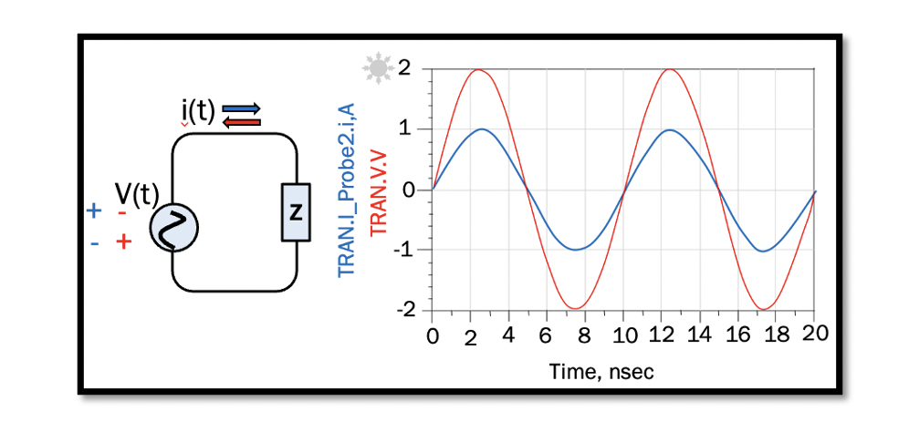
Analysis of Power and Phasor in RF systems
The RF circuits and blocks are analyzed in terms of power quantity; hence, in RF systems, we are more concerned about the power quantity rather than the voltage and current, for example, the power gain, which is the ratio of input to output power. Read more about power ‘Understanding instantaneous and average power’.
The representation of a sinusoidal wave in terms of amplitude and angular frequency is called phasor. In RF systems, it is crucial to know the calculations using phasor as the main aim here is to find the most stable waveform of voltage and current. Phasor is represented as a complex number shown below, where A is amplitude, ω is the angular frequency and θ is the phase:

For example, 2cos(ωt + 30°) can be represented as 2ej30°, where 2 is the amplitude, and 30° is the phase.
Impedance is similar to resistance measured in ohms; however, impedance is the measure of total resistance offered by an electric circuitry considering the inductance and capacitance. In RF systems, impedance is a complex number with real and imaginary values and measured as the ratio of phasor voltage to phasor current. Admittance, on the other hand, is the opposite of impedance. It is the measure of the ease of current flow in a circuit, measure in mho (℧). In order to design RF circuitry and matching circuits, the fundamental concept of impedance and admittance of these three elements (R, L, C) concerning frequency make the vital aspects of RF systems.
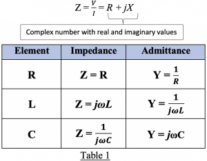 Analysis of phasor and impedance
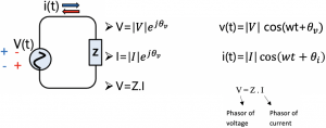
In the circuit shown above, the power source is AC, and the current changes the polarity. The voltage (V) and current (I) in this circuit have phase and amplitude and can be expressed in terms of phasor voltage and phasor current. When analyzing a circuit with impedance, the phasor values of the current and voltage is required to calculate the average power.
Example 1: Circuit with pure resistance
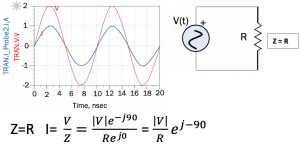
In the graph above, the two sine waves represents the voltage and current, and they have the same phase but different amplitudes. The blue wave has an amplitude of 1, and the red wave has an amplitude of 2. In phasor, the sine wave is converted into cosine. Hence, the sine wave with an amplitude of 2 can be written as: 2 sin(ωt) = 2 cos(ωt-90). As this is a pure resistive circuit the impedance (Z) is pure resistance; therefore, Z = R, the imaginary part phase is 0, as it is the real value. Converting the current into phasor current, we get the amplitude of current and phase of the current. As we see, there is no phase shift. Both current and voltage have the same value, which is -90.
Example 2: Circuit with pure inductance (imaginary impedance)
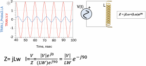
From table 1, we know that Z= jLω for inductance. In this circuit with inductor L, the impedance is represented in phasor as (Lω)ej90. Here, the voltage is a cosine wave with an amplitude of 2. The blue wave representing the current wave in this circuit has a phase difference of 90° with the voltage. In real impedance, the voltage and current will have the same phase as shown in example 1; however, if there is pure imaginary impedance or complex value with real and imaginary impedance in the circuit, the phase changes. There will be a phase difference between current and voltage waves, as shown in this example 2.
Representing power in terms of phasor
The instantaneous power in a circuit can also be represented in terms of phasor as shown below:

Similarly, the average power can be represented in terms of phasor using the above equation 1. Read more about average power. The formula for average power is:

Finding the RMS values of current and voltage and replacing them in equation two, we get the average power in terms of RMS values:

To conclude, for a pure imaginary circuit the phase difference is 90 as shown in example 2, and hence the average power (Pave) will be 0, since, cos 90 is equal to 0. The average power for any pure imaginary circuit with inductance or capacitance is always 0.

Learn more about this topic by taking the complete course ‘’RF Design Theory and Principles – RAHRF201’’.
Watch the course videos for more detailed understanding. Also checkout other courses on RF system and IC design on https://rahsoft.com/courses/
Rahsoft also provides a certificate on Radio Frequency. All the courses offer step by step approach.
Tag:Average power, Impedance, Phasor, Power, RF systems, RMS


