Drawbacks of Direct Conversion Receivers – Flicker Noise
What is Flicker Noise?
Previously we discussed different categories of noise (pink, white, and band-limited noise). Different types of noise can be specific to devices. Read about types of noise in RF devices.
Flicker Noise is one of the types of noise that occurs in almost all the electronic components and is inversely proportional to frequency. If the frequency increases, the flicker noise decreases. It often occurs as resistance fluctuation.
What is Power Spectral Density (PSD)?
The frequency domain view gives more information and insights and is considered more useful in RF design. Therefore, we go through the power spectral density function (PSD).
The PSD of a signal describes the power present in a signal as a function of per unit frequency. It shows the relationship between power and frequency. PSD also shows the variations in strength as a function of frequency. In other words, we can say that PSD shows the frequency variations at which they are strong or weak. PSD is always representing power in 1Hz, therefore the bandwidth was limited to 1Hz. If we take the integral of PSD, it is actually Paverage and the area under PSD equals average power.
How Flicker Noise affects the receiver?
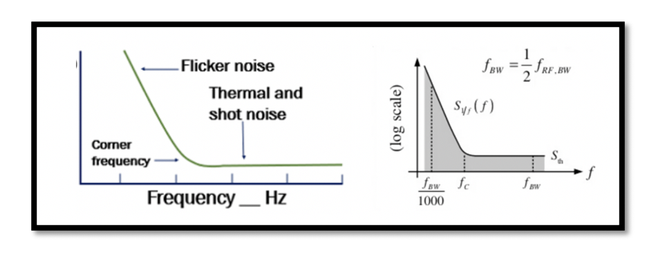
The most important issues that we face in designing a zero IF receivers and it is the flicker noise. This issue is not only for the direct conversion receivers, it is for receivers that works with a zero IF, it means we are trying to translate our channel to very low frequency and is called zero IF. When the channel is around zero frequency it has a very low frequency data, and as we know that the flicker noise is dominant in low frequency, we can say that the Power Spectral Density (PSD) is inversely proportional to the frequency. So as the frequency decreases the noise gets dominant. This increased flicker noise will now become a problem as it will affect our channel. Though the signal is amplified by LNA and mixer, the downconverter signal is still small and is affected by noise in the baseband circuits. The downconverters signal means zero IF, because if the signal gets translated to the intermediate frequency, we will not have a flicker noise problem as we know that the flicker noise is only dominant in low frequency. There are four defined parameters for this:
At the beginning as shown in the above figure flicker noise is dominant as it is inversely proportional to frequency but when we increase it we reach a point called fc, the corner frequency. It is assumed that after fc we don’t have any flicker noise, that is the frequency is high enough and the PSD of flicker noise is approaching zero. Hence, after fc there is only thermal noise. At corner frequency we can say that PSD of flicker noise is equal to PSD of thermal noise.
What is Thermal Noise?
Thermal noise occurs due to temperature, which leads to the random movement of charges- typically electrons in a conductor.


