Image rejection in Low IF Receiver
From a previous blog about low IF receiver we know that it has an image problem as it’s not zero IF anymore so the signal won’t be translated around the baseband so we will have an image problem. In order to get rid of the image problem in a low IF receiver we will need an image rejection receiver. Therefore, we need to design an image rejection receiver.
The two methods to design image rejection receiver for Low IF:
- Design using RC-CR Network
- Digital solution
1. Design using RC-CR Network
In previously discussed blogs we talked about the RC-CR network but this time we won’t be using the weaver structure as the weaver structure has a secondary image problem. Some of the questions answered in this section are:
Why cannot we use the weaver structure for low IF?
Why RC-CR is a good choice for image rejection in low IF?
In zero-IF it is possible to use a weaver structure, the channels should be symmetrical in that case and if it is not symmetrical, we have to design quadrature structures. All these have been previously discussed in our blogs. In the current scenario, as we already know that we have low IF and not zero IF, we have to design a weaver structure with two steps mixers, we cannot design quadrature as it’s not a baseband and we will definitely have a secondary image now. So it’s not a good idea to use a weaver structure for low IF. Hence, we will go with the RC-CR network which is a good choice for image rejection. RC-CR Network is one of the methods to implement a 90-degree phase shift in a receiver. RC-CR network uses two filters high pass filter (CR) and low pass filter (RC).
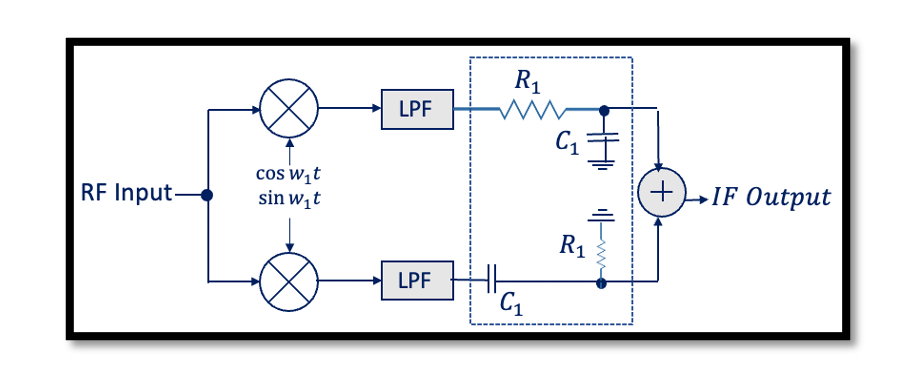
However, there is a problem when using the RC-CR network for low IF receivers. When we discussed about RC-CR network we showed the below structure.
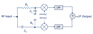
The problem is, previously we were working in IF frequency and the channel was somewhere here as shown in the diagram below. But now what happens is that the channel has low IF so the down-converted channel will have a low center frequency. Hence, we have to bring up this point and choose a bigger value for R and C, but there is no guarantee because the high pass filter has to be very sharp to allow our channel which is very difficult to design. Therefore, we need to find another solution for this. The solution is to move the RC-CR part to the beginning of the architecture, that is move the 90˚ phase shift from the IF path to the RF path. So now we have an RF signal for RC and hence we can design 1/R1C1, it’s high frequency and it won’t have the aforementioned problem in the design. Our channel is not down-converted at this point so it’s a good idea to move back this RC-CR network in order to implement a 90˚ phase shift.
2. Digital solution
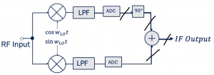
The next method to design a receiver with image rejection for low IF is moving completely into the digital domain. As shown in the diagram the data can be digitized by doing digital signal processing and have a 90˚ phase shift. There will not be any problem with the analogue phase shift. There is a problem here as well, it might be known to the designers of ADC. ADC must accommodate a signal bandwidth twice of that in a DC receiver which means more power. However, it is not important for narrow channels like GSM. This topic is not explained in detail as we are focused on the first method, but we wanted to share an alternate solution as well.


